High-Reliability Rigid-Flex PCB Manufacturing & Assembly
Class 3 Medical & Aerospace Grade | Dynamic Flexing up to 100,000+ Cycles | IPC-6013 Standard
- 0.15mm Ultra-Thin Flex Zone
- Adhesiveless Pyralux AP Core (No Delamination)
- Biocompatibility & Disinfectant Resistant
Request a Quick Quote
ISO 9001:2015
Certified Quality Control
ISO 13485
Medical Device QMS
IPC-6013 Class 3
Medical & Military Standard
RoHS & CE
Fully Compliant
100% E-Testing & TDR
Impedance Control
Rigid-Flex PCB Types by Layer & Structure

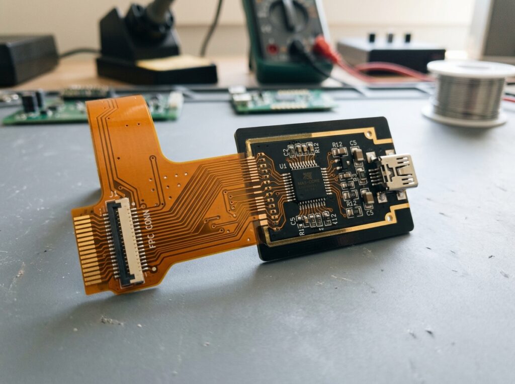
Single-Sided Rigid-Flex
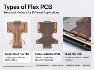
The simplest rigid-flex architecture: a single conductive copper layer on the flex substrate, permanently bonded to rigid FR4 sections. It replaces discrete wires and ribbon cables with one unified, bendable circuit for straightforward point-to-point connections.
- Lowest-cost entry into rigid-flex, fast to prototype and manufacture
- Eliminates connectors and cable harnesses in compact consumer devices
- Ideal for low-speed signals, battery links, and simple sensor interfaces
Double-Sided Rigid-Flex
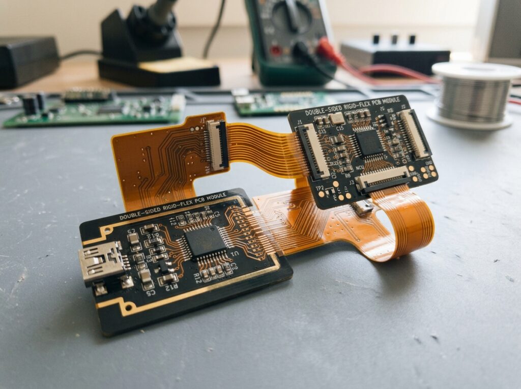
Two conductive copper layers — one on each side of the flex substrate — interconnected via plated through-holes (PTHs). This structure doubles routing density without increasing flex thickness, giving designers far more freedom in space-constrained layouts.
- Doubles routing capacity while keeping the flex core ultra-thin
- PTH interconnections ensure reliable signal crossover between layers
- A balanced choice for cameras, wearables, and handheld electronics
Multi-Layer Rigid-Flex
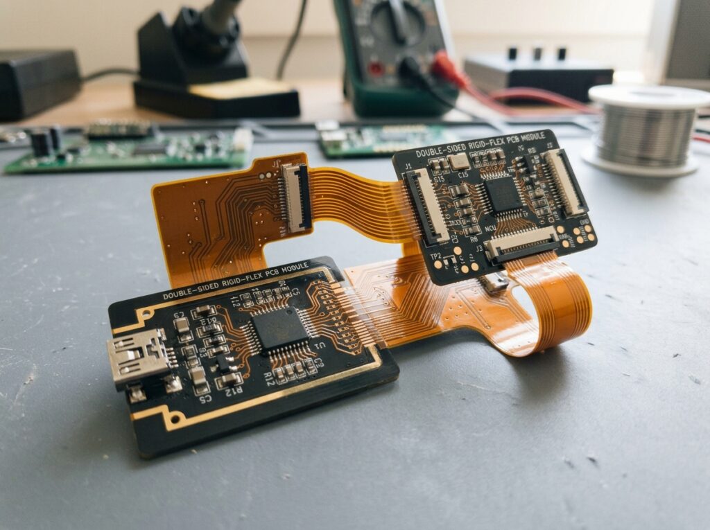
Uses three or more conductive copper and flex layers interconnected with PTHs, blind vias, or buried vias. This type handles complex signal routing, impedance control, and high component density in a single integrated 3D assembly.
- Supports complex signal routing and controlled impedance design
- Blind and buried vias free up surface area for dense component placement
- The workhorse structure for industrial, medical, and aerospace electronics
High-Density Interconnect (HDI) Rigid-Flex
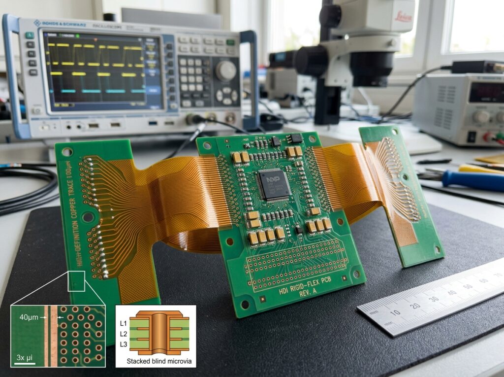
The most advanced rigid-flex class, integrating laser-drilled microvias and complex stacked or staggered via structures (such as 2+n+2 builds). It packs maximum interconnect density into minimal volume for cutting-edge miniaturized electronics.
- Laser microvias enable fine-pitch BGA fan-out down to 0.4 mm
- Stacked and staggered via structures maximize routing in minimal space
- Built for smartphones, implantable medical, and aerospace-grade devices
Rigid-Flex PCB vs Flex PCB vs Rigid PCB
FULL COMPARISON GUIDE (2026 ARCHITECTURE & SELECTION)
| KEY PARAMETERS | Rigid PCB Standard Board | Flex PCB Flexible Circuit | RECOMMENDED Rigid-Flex PCB Hybrid Integration |
|---|---|---|---|
Base Material Substrate Composition | FR-4 / High-Tg FR-4 | Polyimide (PI) Film | Integrated FR-4 + Polyimide |
Flexibility & Motion Mechanical Behavior | Non-bendable(Rigid 2D Structure) | Dynamic Bending(Twist, Fold & Curve) | Hybrid 3D FoldingRigid Mount + Flex Routing |
Interconnect Method Board-to-Board Connections | Connectors, Headers & Wire Harnesses | ZIF Connectors or Direct Tail Soldering | ZERO Cables & Harnesses |
Shock & Vibration Harsh Environment | Moderate Risk(Solder joint fatigue) | High Flexibility(Absorbs kinetic shock) | MAXIMUM ReliabilityNo Interconnect Failure Points |
Cost Structure Bare Board vs. Total System | Bare Board: LowestHigh manual cable assembly | Bare Board: ModerateModerate assembly cost | Bare Board: HighestLowest Total Assembly Cost(Reduced BOM + Labor) |
Primary Applications Best Use Cases | Consumer Electronics, Power Supplies, Motherboards | Foldable Displays, Cameras, Printer Heads, Sensors | Aerospace, Medical Implants, EV BMS / ADAS, Wearables |
| Source: Electronics Engineering & PCB Manufacturing Standards Guide (2026)DESIGN & SELECTION MATRIX | |||
What is a Rigid-Flex PCB?
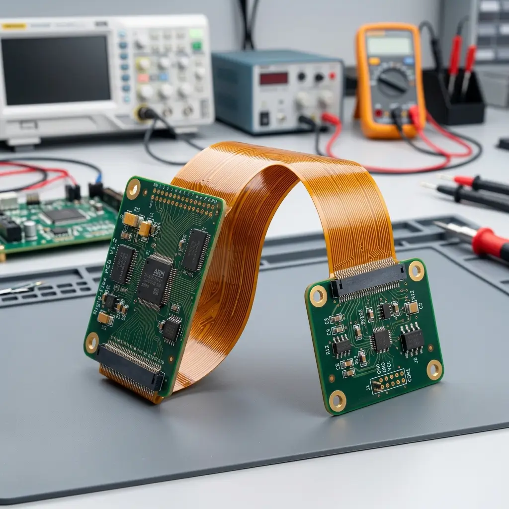
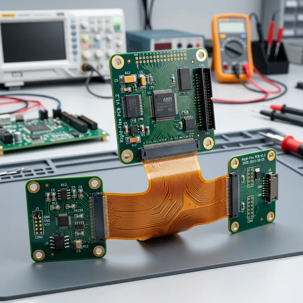
A rigid-flex PCB is a hybrid board that merges standard rigid substrate layers with flexible circuitry into a seamless, unified 3D assembly.
- Rigid Sections: Built primarily from FR4 fiberglass, providing stable support for heavy components, dense ICs, and standard interfaces.
- Flexible Sections: Constructed using ultra-thin polyimide (PI) film and rolled copper, enabling twisting and bending within constrained layouts.
- Integrated Structure: Permanently laminated together to eliminate external cables, wire harnesses, and board-to-board connectors.
Key Advantages
- Space and Weight Reduction: Eliminates bulky wires and connectors, shrinking the overall footprint in tight enclosures.
- Higher Reliability: Fewer physical connectors and soldered joints mean fewer potential points of failure from vibration or mechanical stress.
- 3D Design Freedom: Allows circuits to bend around corners, fold like origami, and fit custom or irregular 3D shapes.
- Improved Signal Integrity: Consistent material properties and fewer interface transitions enhance electrical performance.
Why Choose Rigid-Flex PCBs
Topfast delivers high-reliability rigid-flex solutions that maximize performance in compact designs.
- Space Saving
60% smaller than traditional boards with wiring harnesses
- Design Flexibility
Bend and fold to fit complex geometries
- High Reliability
100,000+ flex cycles with no connection failures
- Durability
Withstands extreme temperatures up to 300°C
Core Advantages
Extreme Space & Weight Savings: Enables 3D folding and eliminates interconnect connectors, reducing system footprint and reducing wiring weight by up to 60–70%.
Superior Reliability & Shock Resistance: Replaces failure-prone solder joints and headers with continuous flex traces, resisting harsh vibration and mechanical impact.
Optimized Signal Integrity: Continuous trace routing across layers ensures stable controlled impedance, lower insertion loss, and strong EMI shielding.
Lower Total Cost of Assembly (TCO): Higher raw PCB cost is offset by reduced BOM component counts, simpler manual assembly, and zero risk of miswiring.
Proven Case Study
What is rigid-flex PCB design?
Â

Target Application
Minimally Invasive Medical Device (Endoscopic Controller)
Technical Challenge
High dynamic bending cycles in an extremely tight space, combined with strict chemical wipe resistance requirements for hospital disinfection protocols.
Structure
6-Layer Rigid-Flex (2 Rigid + 1 Flex + 2 Rigid) hybrid stackup.
Topfast Manufacturing Solution
- ✓ Material Selection: DuPont Pyralux AP Adhesiveless PI base with Rolled Annealed (RA) Copper foil.
- ✓ Flex Zone Optimization: 3-layer flex zone stackup, coverlay openings shifted off the bending centerline.
- ✓ Stiffener Design: 0.1 mm PI stiffener applied to connector zones for optimized stress relief.
- ✓ DFM Review: Full pre-production DFM analysis covering bend radius, grain direction and plating reliability.
Verified Results
- ✔ 50,000+ Bending Cycles: Impedance shift < 5% after 60,000 dynamic test cycles.
- ✔ Chemical Resistance: Passed 100+ medical-grade disinfectant wipes with zero delamination.
- ✔ Compliance: Fully compliant with IPC-6013 Class 3 & Biocompatibility declarations.

Why Choose Topfast
Designed for Extreme Reliability in Space-Constrained Applications
Up to 60% Space Saving
Eliminates heavy wire harnesses and connectors, dramatically reducing enclosure dimensions and overall system weight.
100,000+ Dynamic Flex Cycles
High ductility Rolled Annealed (RA) copper prevents trace micro-cracking during constant bending.
Thermal & Chemical Durability
Withstands temperatures up to 300°C and harsh chemical disinfection without layer separation.
Rigorous DFM & Quality Control
100% AOI, E-testing, Microsection analysis, and TDR impedance testing before shipment.
Ready to Start Your Rigid-Flex PCB Project?
Upload your Gerber files today for a professional DFM review and detailed cost analysis within 24 hours.
Request a Quick Quote
Upload your Gerber files — DFM review & quote within 24 hours.
Engineering Capability
Technical Specifications & DFM Capabilities
| Parameter | Metric Value | Imperial Value | Feature Highlights |
|---|---|---|---|
| Layer Count | 2 - 20 Layers | 2 - 20 Layers | Rigid-Flex Hybrid Stackup |
| Min. Core Thickness | 0.051 mm | 0.002″ | Ultra-thin Polyimide Core |
| Min. Trace / Space | 0.089 mm (3.5 mil) | 0.0035″ | High-Density Fine Line |
| Smallest Drill (Mech/Laser) | 0.18mm / 0.127mm | 0.0071″ / 0.005″ | Microvia / Blind & Buried Vias |
| Max Aspect Ratio | 10:1 | 10:1 | Reliable Plated Through Holes |
| Finished Copper Weight | Up to 3 oz (89 μm) | Up to 3 oz | High Current Capacity |
| Flex Zone Stiffener | 0.1mm PI / Stainless / FR4 | Custom Stiffeners | Optimized Stress Relief |
Premium Substrates & Surface Finishes
- Base Material: DuPont Pyralux AP (Adhesiveless) + RA Copper for high dynamic flex endurance
- Adhesives & Stiffeners: Acrylic / Epoxy high-bond adhesives, PI Stiffener, FR4 Stiffener
- Surface Finishes: ENIG, Immersion Silver, OSP (Shikoku F2), Selective Hard Gold
Surface Treatment Options
✔ HASL (Vertical or Horizontal)
✔ Lead-Free HASL
✔ OSP (Shikoku F2)
✔ OSP (Entek)
✔ ENIG (Electroless Nickel Immersion Gold)
✔ Immersion Silver
✔ Immersion White Tin
✔ Tin-Nickel
✔ Electrolytic Soft Gold
✔ Electrolytic Hard Gold
✔ Selective Gold
Surface Treatment Options
Â
| Parameter | Metric Value | Imperial Value |
|---|---|---|
| Min Core Thickness | 0.051 mm | 0.002″ |
| Max Finished Copper Weight | 89 ml | 3 oz |
| Max Finished Copper Thickness | 0.009 mm | – |
| Smallest Mechanical Drill | 0.180 mm | 0.0071″ |
| Smallest Laser Drill | 0.127 mm | 0.005″ |
| Min Finished Hole Size | 0.152 mm | 0.006″ |
| Max Through Hole Aspect Ratio | 10:1 | – |
| Max Blind Via Aspect Ratio | 0.75:1 | – |
| Min Trace/Space (Rigid) | 0.089 mm | 0.0035″ |
| Min Pad Size for Test | 0.127 mm | 0.005″ |
| Material Type | Example / Subtype | Function |
|---|---|---|
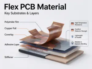
| Conductors | Rolled Annealed (RA) Copper | Used in flexible circuits requiring repeated bending. It offers superior ductility, a grain structure aligned with the bend axis, and a reduced risk of micro-cracking. |
| Electro-Deposited (ED) Copper | Preferred in rigid sections and some static flex zones. Provides high conductivity and fine trace definition but lower flex fatigue performance than RA copper. | |
| Adhesives | Epoxy | Strong adhesion with low moisture absorption. Tg typically ≥135 °C. Commonly used between copper and dielectric layers in rigid zones. |
| Acrylic | High peel strength, chemical resistance, and thermal stability (Tg ~150 to 200 °C). Often selected for rigid-flex bonding interfaces. | |
| Pressure Sensitive Adhesive (PSA) | Low-temperature bonding layer is used to attach stiffeners or mount flex circuits. Limited to non-electrically active zones. | |
| Polyimide (as adhesive) | Extreme thermal resistance (>250 °C) and chemical durability. Used in aerospace-grade flexible PCB assemblies exposed to harsh environments. | |
| Adhesiveless Base Material | Polyimide is cast directly onto copper foil. Eliminates adhesive interface, improves flexibility, reduces Z-axis expansion, and enhances thermal reliability in dynamic flex circuits. | |
| Pre-preg (Resin-coated Glass) | Â | Dielectric bonding sheet used during multilayer lamination in rigid areas. Properties depend on the resin system (Tg, flow, Dk/Df). |
| Insulators / Dielectrics | FR-4 | Standard rigid PCB core. Tg typically 135 to 170 °C. It provides mechanical support and a routing platform for rigid flex boards. |
| Polyimide | High-flex, high-temperature material (Tg >250 °C). Used in flexible sections due to superior bend endurance and dimensional stability. | |
| CEM-1 | Cellulose-based composite alternative to FR-4. Used in cost-sensitive rigid sections with low mechanical stress. | |
| Polyester (PET) | Flexible and thermally stable (~120 to 150 °C), lower cost than polyimide. Used in basic flexible PCB assemblies. |
FAQ
Frequently Asked Questions
A rigid-flex PCB is a hybrid circuit board that seamlessly integrates rigid board sections (FR-4) with flexible substrate layers (Polyimide) into a single unified 3D assembly. It allows components to be mounted on rigid zones while flexible sections bend or fold to fit compact enclosures.
Rigid-flex PCB design is the engineering process of planning multi-layer stackups, signal routing, and transition zones between rigid and flex substrates to ensure electrical performance, thermal stability, and mechanical durability across static or dynamic bends.
Rigid PCB: Completely stiff, relies on external wire harnesses and connectors to join multiple boards.
Flex PCB: Thin and flexible throughout, designed for light weight and continuous dynamic flexing.
Rigid-Flex PCB: Combines both into one piece, eliminating connectors and wiring entirely for true 3D spatial folding.
A flex PCB with a rigidizer uses localized stiffeners (FR-4, aluminum) purely for mechanical support under SMT components or connectors without extra conductive layers. In contrast, a rigid-flex PCB features integrated multi-layer conductive circuits running continuously through both rigid and flex regions.
Rigid-flex PCBs eliminate bulky wire harnesses, reducing interconnect failure points, system weight, and volume. They provide superior resistance to shock and vibration, optimized signal integrity (controlled impedance), and lower total assembly labor costs.
We support customized rigid-flex PCB designs from 2 up to 20 layers, including complex HDI, blind/buried vias, and asymmetric rigid-flex stackups.
Key challenges include managing material expansion/contraction across dissimilar substrates (FR-4 vs. Polyimide), achieving precise layer registration during multi-stage lamination, controlling unbonded flex regions, and controlling thermal stress during soldering.
Please provide your Gerber files (including layer stackup and flex zone definitions), PCB quantity, surface finish requirement, copper weight, and stiffener specs.
Yes, upon request, we provide full quality verification reports including TDR impedance test reports, microsection analysis, and dynamic flex test data.
Our factories are ISO 9001, ISO 13485 (Medical Devices), ISO 14001, UL, and RoHS certified. All rigid-flex boards meet IPC-6013 Class 2 and Class 3 standards.
Overall board thickness varies depending on layer count and application:
Flex sections: Typically $0.002\text{ to }0.010\text{ inches}$ ($0.05\text{–}0.25\text{ mm}$).
Rigid sections: Standard thickness ranges from $0.016\text{ to }0.093\text{ inches}$ ($0.4\text{–}2.4\text{ mm}$), commonly $1.6\text{ mm}$ ($0.062\text{ inches}$).
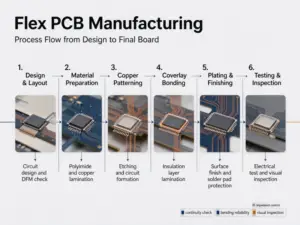
The manufacturing process involves preparing polyimide inner cores, etching flex circuits, applying polyimide coverlays, pre-assembling with FR-4 rigid layers, executing multi-stage lamination, laser/mechanical drilling, plating through-holes, and routing rigid outer contours.
Common configurations range from single-sided flex with rigid stiffeners, traditional 4–12+ layer symmetrical stackups, embedded/flex-cap structures, air-gap unbonded flex layers for dynamic bending, to High-Density Interconnect (HDI) rigid-flex boards with laser microvias.
Key rules include avoiding vias/pads in flex transition bend zones, keeping copper traces perpendicular to bend lines, using teardrops on pads, maintaining a minimum bend radius ($10\text{–}12\times\text{ flex thickness}$ for dynamic flex), and using hatched copper planes instead of solid planes in flex zones.