High-Speed PCB Manufacturing for 400G Optical Module Backplanes
112 Gbps PAM4 Ready | 16-Layer Megtron 6 | Stub < 10 mil Backdrill Control
- 100 Ω ± 8% Differential Impedance
- Eye Margin > 25% at 112 Gbps PAM4
- Controlled-Depth Backdrill ± 0.05 mm
Request a Quick Quote
ISO 9001:2015
Certified Quality Control
Panasonic Megtron 6
Ultra-Low Df < 0.005
IPC-6012 Class 3
Data Center Grade
RoHS & CE
Fully Compliant
100% TDR & VNA E-Testing
112 Gbps Eye Verified
High-Speed PCB Types by Layer Count & Stackup

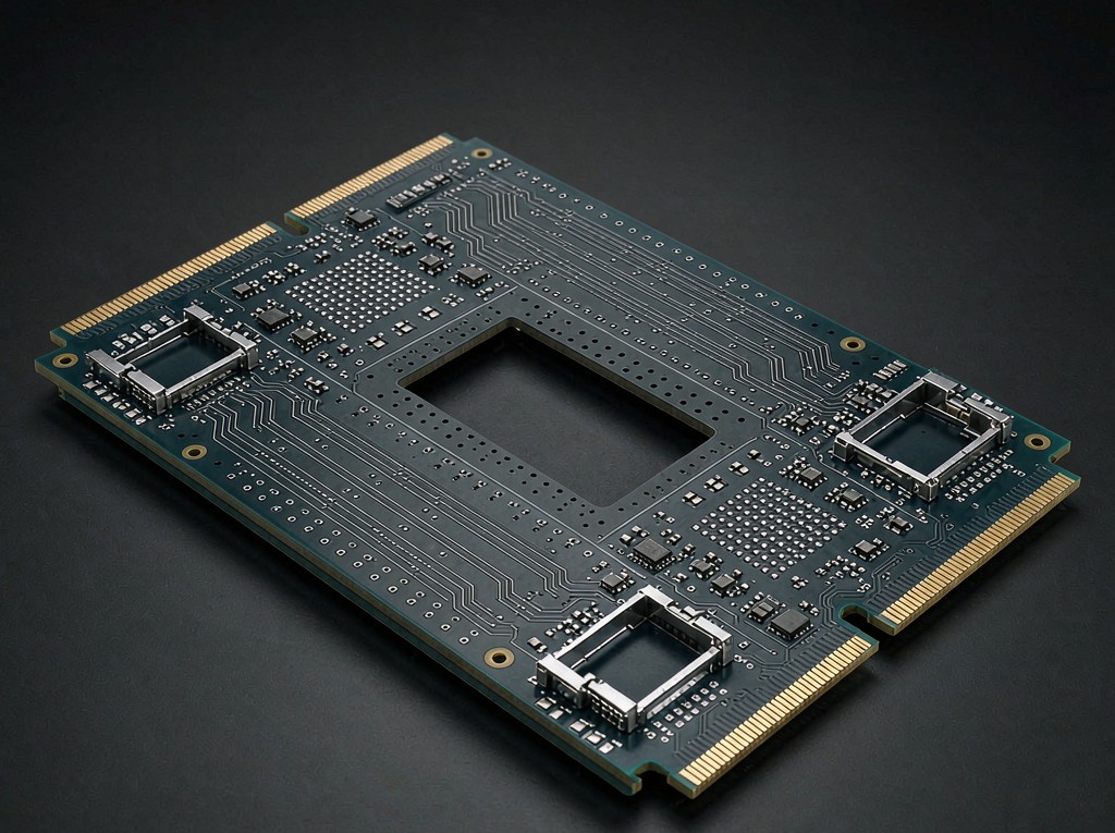
8-Layer Megtron 6 Line Card
The entry point into 112G-class fabrication: eight Megtron 6 layers, 100 Ω differential routing and press-fit connectors, built for line cards and mezzanine modules that do not yet need a full backplane.
- Df below 0.005 keeps channel loss low enough for 56 Gbps NRZ and short-reach 112 Gbps PAM4
- 100 Ω ± 8% differential pairs referenced to solid ground planes on every signal layer
- Fastest route to Megtron 6 performance at the lowest layer count
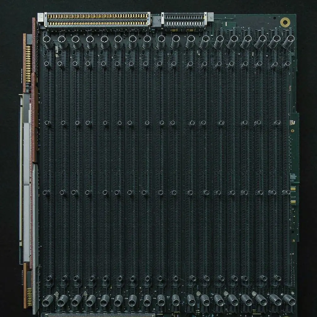
16-Layer Megtron 6 Backplane
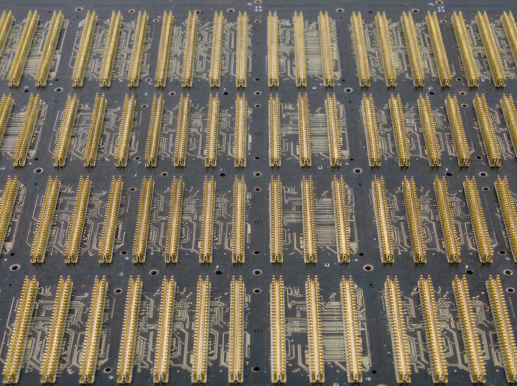
The mainstream 400G architecture: sixteen Megtron 6 layers built as 4 x 4, with long serial links running from press-fit connectors to the optical module. Every through-via on a 112G pair is backdrilled to hold the residual stub under 10 mil.
- The 4 x 4 build keeps signal layers adjacent to a solid reference plane along the whole channel
- Backdrill depth held to ±0.05 mm so stub resonance moves out of the Nyquist band
- Built for 400G optical modules, switch backplanes and AI server trays
20+ Layer Backplane & Daughter Card
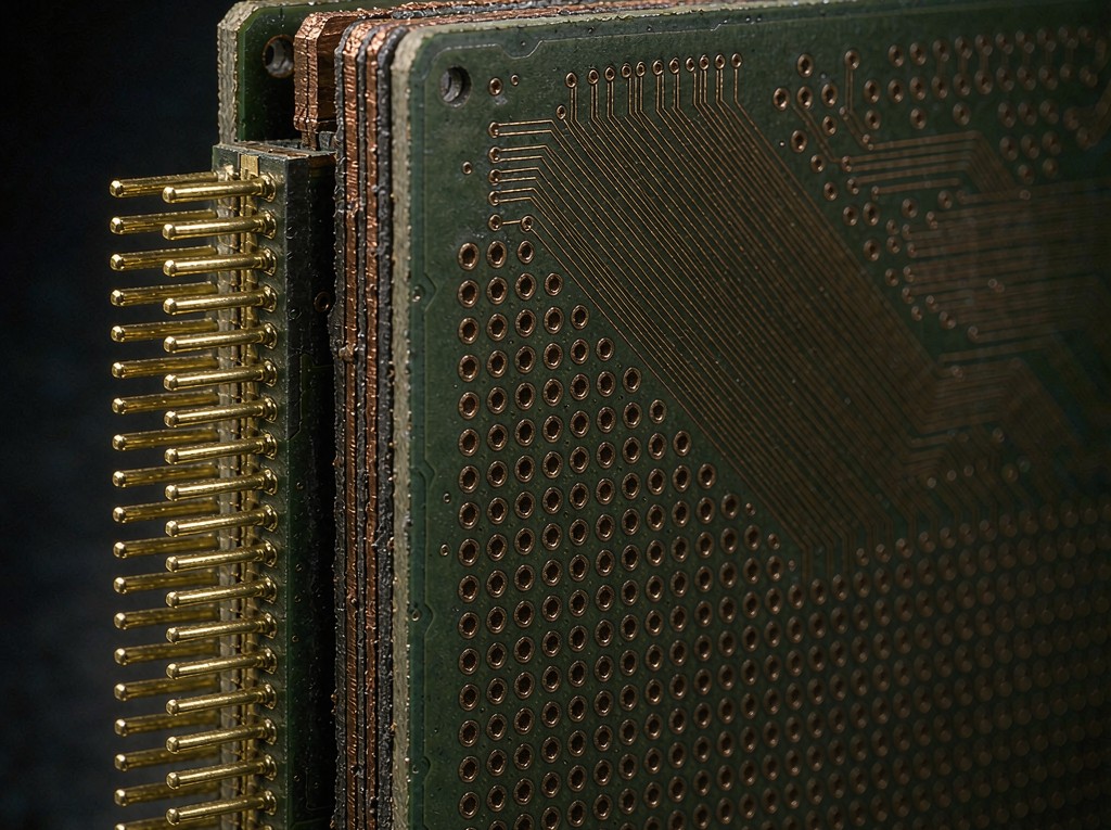
For orthogonal and midplane architectures where layer count carries the channel: twenty to thirty-two Megtron 6 layers, heavy copper power planes and connector fan-outs that must stay inside the 8% impedance window across the full stackup.
- 20:1 aspect ratio plating supports the deepest backplane drills
- Heavy copper planes keep power integrity from disturbing 112G reference layers
- Used in data center switches, AI compute trays and telecom core backplanes
High-Speed HDI PCB
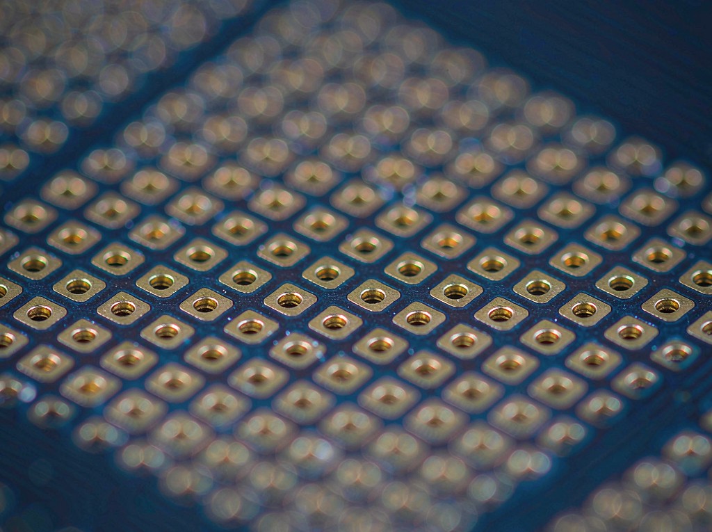
High-speed HDI pairs laser microvias with Megtron 6 so dense logic, power delivery and 112G channels share one board – the architecture behind compact optical modules and co-packaged switch line cards.
- Laser microvias and buried vias remove the stub that a through-hole would leave behind
- Sequential lamination keeps every high-speed layer on a continuous reference plane
- Built for 400G / 800G optical modules and high-density switch line cards
Standard FR-4 PCB vs Megtron 4 vs Megtron 6 Backplane
FULL COMPARISON GUIDE (112 GBPS PAM4 MATERIAL & STACKUP SELECTION)
| KEY PARAMETERS | FR-4 PCB Standard Digital Board | Megtron 4 PCB Mid-Loss High-Speed | RECOMMENDED Megtron 6 Backplane Ultra-Low Loss 112G |
|---|---|---|---|
Base Material Substrate Composition | FR-4 / High-Tg FR-4 | Megtron 4 / IT-180A Hybrid | Megtron 6 / IT-180A Hybrid |
Insertion Loss @ 28 GHz Channel Loss Budget | 0.60 - 0.80 dB/inch(Df 0.015 - 0.020) | 0.35 - 0.45 dB/inch(Df 0.008 - 0.010) | < 0.30 dB/inch(Df < 0.005, eye > 25 %) |
Via Stub Control Residual Stub & Resonance | No backdrill, full stub | Blind vias, partial stub | Full backdrill, stub < 10 mil |
Impedance Tolerance 100 Ω Differential Pairs | ± 10 %(Etch and laminate drift) | ± 8 %(Tight Dk control) | ± 8 % VERIFIEDTDR checked on every layer pair |
Cost Structure Laminate vs. Total System Cost | Lowest laminate cost(SI budget blown, retimer added) | Moderate laminate cost(Tuning loops on thick backplanes) | Highest laminate costLowest total system cost(No retimer, first-pass yield) |
Primary Applications Best Use Cases | Legacy boards below 10 Gbps | 25 / 56 Gbps line cards and mid-range switches | 400G optical modules, 112G switch backplanes, AI trays |
| Source: Panasonic Megtron 6 laminate datasheets, IEEE 802.3ck & IPC-6012 Class 3 fabrication standards (2026)DESIGN & SELECTION MATRIX | |||
What is a High-Speed PCB?
A high-speed PCB is engineered so that every trace behaves as a controlled transmission line: low-loss laminate, tight impedance, continuous reference planes and short via stubs keep the eye open at multi-gigabit data rates.
- Low-Loss Laminate: Panasonic Megtron 6 or Megtron 4 holds Dk and Df stable across frequency, temperature and production lot.
- Controlled Impedance: Every differential pair is designed and etched to 100 Ω ± 8 %, single-ended lines to 50 Ω ± 5 %.
- Short Via Stubs: Through-vias on high-speed layers are backdrilled after plating so the residual stub stays below 10 mil.
Key Advantages
- Lower Insertion Loss: Megtron 6 with Df below 0.005 keeps channel loss under 0.30 dB/inch at 28 GHz Nyquist.
- Wider Eye Opening: Measured PAM4 eye margin above 25 % at 112 Gbps leaves headroom for module and connector loss.
- Tighter Impedance: TDR-verified 100 Ω ± 8 % on every layer pair removes the rework loop after first article.
- Backdrill Discipline: Controlled-depth backdrilling at ±0.05 mm keeps stub resonance out of the Nyquist band.
Why Choose Megtron 6 High-Speed PCBs
Our engineering team pairs ultra-low-loss laminate with backdrill and impedance control so 112G channels pass first time in volume.
- Ultra-Low Loss
Df < 0.005 keeps 28 GHz insertion loss under 0.30 dB/inch
- 112 Gbps PAM4
Eye margin > 25 % verified on the production channel
- Stub < 10 mil
Controlled-depth backdrill on every 112G through-via
- Full SI Validation
TDR, VNA and eye diagram data shipped with every lot
Core Advantages
Ultra-Low Channel Loss: Megtron 6 with Df below 0.005 removes most of the dielectric loss, so a 400G channel closes without adding layers or an active retimer.
Short Stubs, Clean Eyes: Every through-via on a 112G pair is backdrilled to ±0.05 mm depth, moving stub resonance well above the 28 GHz Nyquist band.
Impedance Held Inside 8 %: Stackup, glass-weave skew and etch compensation are controlled together, so differential impedance stays inside ±8 % across sixteen layers.
Validated Before Shipment: TDR profiles, VNA sweeps to 28 GHz, microsections and eye diagram data are supplied with every production panel.
Proven Case Study
How we built a 400G optical module backplane

Target Application
400G Optical Module Backplane (16-Layer Megtron 6)
Technical Challenge
112 Gbps PAM4 channels had to close with eye margin above 25 % across sixteen layers, with every connector via backdrilled and differential impedance held inside ±8 % over the full channel.
Structure
16-layer Megtron 6 stackup built as 4 x 4, 100 Ω differential pairs on L3 – L14, press-fit connectors on both faces.
Slpcba Manufacturing Solution
- ✓ Material Selection: Panasonic Megtron 6 (Dk 3.6 / Df 0.004) on all signal layers, with high-Tg IT-180A FR-4 cores for power and ground to keep the hybrid cost down.
- ✓ Stackup & Via Design: 4 x 4 sequential build with every high-speed layer referenced to a solid plane, and glass-weave-controlled prepreg to hold differential skew low.
- ✓ Backdrill Control: CNC controlled-depth backdrilling at ±0.05 mm, verified by coupon microsection before the panel moves to final inspection.
- ✓ DFM Review: Full pre-production DFM and SI review covering impedance targets, stub budget, press-fit hole tolerance and connector fan-out.
Verified Results
- ✔ Eye Margin > 25 %: 112 Gbps PAM4 eye opening measured above 25 % at the receiver after channel loss, leaving headroom for the optical module.
- ✔ BER < 10⁻¹²: Verified below 1E-12 on the full backplane channel, compliant with IEEE 802.3ck and data center interconnect requirements.
- ✔ Compliance: Zero stub penetration and no barrel micro-cracks in microsection; built to IPC-6012 Class 3 with TDR data supplied per lot.

Why Choose Slpcba
Engineered for 112 Gbps PAM4 Signal Integrity and Repeatable Yield
Stub < 10 mil
Controlled-depth backdrilling removes the unused via copper that would otherwise resonate and close the eye above 14 GHz.
Eye Margin > 25 %
Measured PAM4 eye opening at 112 Gbps leaves headroom for the optical module, connector and cable loss in the channel.
100 Ω ± 8 % Differential
TDR-verified differential impedance on every layer pair, held inside 8 % across the full 16-layer stackup.
VNA + TDR + Microsection
S-parameter sweeps to 28 GHz, TDR impedance profiles and backdrill microsections ship with every production panel.
Ready to Build Your 400G High-Speed Backplane PCB?
Upload your Gerber and stackup files today for a free SI review and a detailed quote within 24 hours.
Request a Quick Quote
Upload your Gerber files — DFM review & quote within 24 hours.
Engineering Capability
Technical Specifications & DFM Capabilities
| Parameter | Metric Value | Imperial Value | Feature Highlights |
|---|---|---|---|
| Layer Count | 4 - 32 Layers | 4 - 32 Layers | High-Layer-Count Backplane |
| Differential Impedance | 100 Ω ± 8 % | ± 8 % | 112 Gbps PAM4 Pair Control |
| Min. Trace / Space | 0.075 mm (3 mil) | 0.003" | Fine-Line 112G Routing |
| Backdrill Depth Tolerance | ± 0.05 mm | ± 0.002" | Stub < 10 mil Guaranteed |
| Max Aspect Ratio | 20:1 | 20:1 | Deep Backplane Drills |
| Finished Copper Weight | 0.5 - 2 oz | 1 oz (typ.) | Low-Loss Conductor Profile |
| Insertion Loss @ 28 GHz | < 0.30 dB/inch | VNA S21 | Megtron 6 Verified |
Premium Substrates & Surface Finishes
- Base Material: Panasonic Megtron 6 (Dk 3.6 / Df 0.004), Megtron 4, ITEQ IT-180A high-Tg FR-4
- Bonding & Hybrid: Megtron 6 prepreg, IT-180A prepreg, plasma pre-treatment before plating
- Surface Finishes: ENIG, ENEPIG, Immersion Silver, OSP, Selective Hard Gold
Surface Treatment Options
✔ ENIG (Electroless Nickel Immersion Gold)
✔ ENEPIG (Electroless Nickel Electroless Palladium Immersion Gold)
✔ Immersion Silver
✔ Immersion White Tin
✔ OSP (Shikoku F2)
✔ OSP (Entek)
✔ Electrolytic Soft Gold
✔ Electrolytic Hard Gold
✔ Selective Hard Gold
✔ Bondable Gold (Wire Bonding)
✔ Gold Finger (30 µin Hard Gold)
Surface Treatment Options
| Parameter | Metric Value | Imperial Value |
|---|---|---|
| Dk Tolerance (Megtron 6) | ± 0.05 | 3.55 – 3.65 |
| Df (Megtron 6, 10 GHz) | 0.004 | < 0.005 |
| Insertion Loss @ 28 GHz | < 0.30 dB/inch | VNA S21 |
| Min. Trace / Space (112G) | 0.075 mm | 0.003″ |
| Differential Impedance | ± 8 % | 100 Ω ± 8 Ω |
| Backdrill Depth Tolerance | ± 0.05 mm | ± 0.002″ |
| Max Board Thickness | 6.0 mm | 0.236″ |
| Layer Count | 4 – 32 L | 2 – 32 L |
| Min Core Thickness | 0.075 mm | 0.003″ |
| Impedance Coupons | 8 per panel | 100 % tested |
| Material Type | Example / Subtype | Function |
|---|---|---|
| Signal & Backplane Laminates | Panasonic Megtron 6 | Ultra-low-loss laminate (Dk 3.6, Df 0.004) for 112 Gbps PAM4 channels. Selected when channel loss and skew, not material cost, set the design limit. |
| Panasonic Megtron 4 | Mid-loss laminate (Df around 0.008) covering 25 – 56 Gbps NRZ links where Megtron 6 is not yet required. | |
| Hybrid & Structural Laminates | ITEQ IT-180A | High-Tg (180 °C) FR-4 for power, ground and mechanical layers in a hybrid build, cutting laminate cost without touching the signal layers. |
| Isola 370HR | Alternative high-Tg FR-4 with proven hybrid lamination compatibility and stable Z-axis expansion on thick backplanes. | |
| Megtron 6 Prepreg | Matched prepreg that holds Dk through the lamination cycle so the 100 Ω target survives every press. | |
| Rogers RO4450F | Bondply used when a design pairs high-speed Megtron layers with PTFE or RO4350B RF sections on the same board. | |
| VLP / HVLP Copper Foil | Very low profile foil (Ra < 2 µm) that lowers conductor loss and skin-effect resistance above 14 GHz. | |
| Backdrill & Via Fill | Controlled-depth CNC backdrilling of connector and press-fit vias to ±0.05 mm, holding the residual stub below 10 mil on every 112G pair. | |
| Dielectric Families | Low-Loss Hydrocarbon | Megtron 4 / Megtron 6 class. Df 0.004 – 0.010 with FR-4-like processing – the mainstream choice for data center backplanes. |
| Ultra-Low-Loss PTFE | Df down to 0.0009 for 28 GHz Nyquist and above; reserved for RF sections and the highest-speed channels. | |
| High-Tg FR-4 | IT-180A / 370HR. Tg 170 – 180 °C, used for power, ground and structural layers in hybrid stackups. | |
| Ceramic-Filled Hydrocarbon | Filled laminates that raise Dk for impedance matching and antenna sections on mixed-signal high-speed boards. |
FAQ
Frequently Asked Questions
A board is high-speed when the signal rise time is short enough that trace length exceeds roughly one sixth of the signal wavelength. From that point the trace behaves as a transmission line, so impedance control, reference planes and via transitions decide whether the link works.
Megtron 6 holds Dk around 3.6 with Df below 0.005, so dielectric loss and phase distortion stay small at the 28 GHz Nyquist frequency of 112 Gbps PAM4. It also keeps Dk stable lot to lot, which matters when sixteen signal layers must match.
Stackup first: Signal layers are referenced to solid ground planes and Dk is fixed by Megtron 6, so pair impedance is calculated rather than tuned on the bench.
Glass-weave skew: High-speed layers use spread-glass prepreg so the fibre-weave effect cannot shift differential skew between pairs.
Etch compensation: Line width is compensated per layer after AOI, holding differential impedance inside ±8 % on every pair.
Each panel ships with TDR impedance profiles, VNA S-parameter sweeps to 28 GHz, backdrill microsections and coupon data. Eye diagram testing can be run jointly with your SI team on request.
On a 100 Ω differential pair with 0.5 oz VLP copper, measured insertion loss typically stays below 0.30 dB/inch at 28 GHz. The exact figure depends on dielectric thickness and the reference-plane scheme.
We build high-speed boards from 4 to 32 layers, including 16- and 20-layer Megtron 6 backplanes, 4 x 4 and 5 x 5 sequential builds, hybrid Megtron / FR-4 stackups and high-speed HDI with laser microvias.
Dielectric loss, conductor loss and via transitions dominate above 14 GHz. Megtron 6 sets the dielectric part, VLP copper sets the conductor part, and backdrilling removes the stub resonance that would otherwise dominate the channel.
Please send Gerber data, the stackup with Dk / Df and impedance targets, backdrill requirements, press-fit and connector specs, board thickness, surface finish and quantity.
Yes. On request we supply TDR impedance profiles, S11 / S21 sweeps to 28 GHz, backdrill microsection images and PAM4 eye diagram measurements from the production channel.
Our factories hold ISO 9001, ISO 14001, UL and RoHS certification, and all high-speed backplanes are built to IPC-6012 Class 2 or Class 3.
Thickness follows the geometry you need for 100 Ω differential pairs:
16-layer backplanes typically 2.0 – 3.2 mm (0.079 – 0.126″);
20-layer backplanes range from 3.2 – 4.5 mm (0.126 – 0.177″), commonly 4.0 mm (0.157″).
Megtron 6 cores and prepreg are baked, plasma-treated and laminated in a 4 x 4 sequential build, then drilled, plated and backdrilled to depth. Outer layers are imaged on VLP copper, followed by coupon impedance measurement, TDR profiling and VNA verification before shipment.
Common configurations include 8-layer Megtron 6 line cards, 16- and 20-layer backplanes, 4 x 4 and 5 x 5 sequential builds, hybrid Megtron / IT-180A stackups and high-speed HDI with laser microvias.
Keep every 112G pair on a continuous reference plane, avoid plane splits under connector fan-out, specify backdrilling on all through-viasstub < 10 mil and define glass-weave skew limits plus impedance coupons on the fabrication drawing.