
Enclosures keep getting thinner while the electronics inside grow. A phone carries several camera modules and a battery that fills most of the internal volume, and a car door module packs sensors, lighting and a motor driver into the space that once held a window switch. Rigid boards handle that density until the geometry stops being flat. Once a design has to fold around a battery or cross a gap that vibrates, the flat board gets split into pieces and joined with cables, which is usually when the drawing goes to a custom flexible PCB supplier for a feasibility check.
The advantages of flex PCBs come down to two things: mechanical freedom and fewer interconnects. A flexible PCB board follows the shape the product leaves available instead of forcing the housing to accommodate a flat board, and it replaces the cable-and-connector chain between boards with continuous copper. Space, weight, assembly time and field reliability improve because of those changes, not as separate features. Electrical performance is usually a secondary benefit rather than the reason a team switches.
The first advantage worth looking at is the one that decides everything downstream.
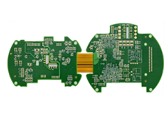
How flex circuits change the mechanical layout
A flexible circuit turns the layout from a flat plane into a formed part. The board follows the housing, wraps around what is already inside it, and folds so two circuit areas stack over each other, which stops the design competing with the enclosure for room.
Three arrangements dominate production. A fold puts two circuit areas back to back with a bend between them. A wrap sends the circuit around a battery, a lens barrel or a handle. A hinge leaves a section free to move whenever the product moves. Each loads the copper differently, so the same laminate can behave well in one and fail early in another.
Folding instead of stacking
Two rigid boards sitting side by side need a gap, mounting hardware and a cable with two connectors. A fold replaces that with a strip of copper, and the only constraint left is component height: parts inside the fold have to clear each other, so tall parts stay off one side and the stiffener sits outside the bend.
What the thinner stack buys you
A typical rigid board runs about 1.6 mm. Commercial flex builds land between 0.05 mm and 0.5 mm, with 0.8 mm available for heavier copper or more layers. Losing a millimetre of board height changes what else fits: a larger battery, a bigger speaker, a lower camera bump. Weight drops with it, because the dielectric is polyimide film instead of glass-reinforced epoxy.
Where flex removes failure points
In a rigid assembly, most interconnect failures start at connectors and solder joints. Every mating pair adds contact surfaces, plating wear, and two materials expanding at different rates. A flexible PCB circuit replaces that chain with continuous copper, so the failure location disappears instead of being reinforced.
Take the link between a main board and a display in a folding product. A rigid-plus-cable design has a board-to-board connector, a cable, a second connector and a solder joint at each end, and any one of them can start a crack under vibration. A single flex has no mating interface in the middle; copper runs pad to pad, and the only joints sit on stiffened areas that do not move.
Vibration matters as much. Automotive and industrial PCB electronics see constant low-amplitude movement, and a plugged connector under that load wears through its plating. A flex built for dynamic service is designed for it, with bend radius, copper type and coverlay chosen for cycles rather than installation.
Signal behaviour improves for a related reason: flex has no woven glass, so the dielectric constant stays uniform along the trace and the bend has no connector stub in the middle. A flex does not fix a badly designed channel, though, and impedance still has to be calculated for the actual stack.
Which applications justify the switch
Flex earns its place when something moves, folds, or has to fit into a space too thin for a rigid board. The industry matters less than the mechanical situation inside the product.
| Application area | What drives the choice | Typical part |
|---|---|---|
| Phones and foldables | Hinge travel, camera modules, display connection | Display flex, camera flex, hinge flex |
| Wearables | Skin contact, weight, sealed enclosure | Sensor flex, antenna flex, button flex |
| Automotive | Vibration, heat, harness replacement | Battery management, lighting, sensor leads |
| Medical | Catheter and endoscope bending, single-use assemblies | Sensor flex, imaging flex, disposable patches |
| Industrial and instruments | Print heads, moving carriages, tight routing | Head cable, encoder flex, control interconnect |
| Aerospace | Weight limits, reliability under vibration | Avionics interconnect, sensor harness |
Most products end up using both: a phone has rigid boards for the processor and flex for anything that crosses a hinge.
Flexible PCB materials and thickness: what sets bend performance
How tight a flex can bend, and how long it lasts, comes from the flexible PCB material you pick and how it is stacked: substrate, copper type, coverlay, stiffeners and finished thickness. Flexible PCB thickness on its own tells you very little, because two 0.2 mm parts can have very different flex life.
| Property | Polyimide (PI) | Polyester (PET) |
|---|---|---|
| Temperature resistance | High, up to roughly 400 °C for short excursions | Moderate, around 150 °C |
| Cost | Higher | Lower |
| Flex life | Good, suited to dynamic bends | Limited, better for static bends |
| Typical use | Automotive, medical, industrial, multilayer | Low-cost static assemblies, simple consumer parts |
Polyimide dominates for a reason that has little to do with flexibility: it survives soldering. PET distorts in reflow, so it appears in parts joined by pressure contact or crimp. Copper choice matters as much: rolled annealed copper tolerates repeated bending, while electrodeposited copper costs less and suits a part that bends once.
Protection above the traces comes in two forms. Coverlay is laminated polyimide film with adhesive, and it handles bends better because it belongs to the same material family as the substrate. Photoimageable solder mask gives finer openings and costs less but cracks sooner, so many designs run coverlay in the bend and mask on the stiff areas.
A stiffener solves a different problem. A flex is too floppy to hold a connector or spread a screw load, so FR4, polyimide or stainless steel is laminated to the back to stiffen that area alone. The catch is the edge: the step in stiffness is where cracks begin.
Static bends and dynamic bends are different designs
A part that bends once at assembly can use a tight radius, thinner copper and a simple stack. A part that flexes every time the product is used needs a larger radius, rolled copper, symmetrical construction and no plated holes near the bend. The drawing has to state which case applies, because a part quoted as static and installed in a hinge passes every test on day one and cracks months later. The IPC design standards treat flexible and rigid-flex boards under a separate sectional standard, IPC-2223, because the radius requirement changes with the construction and the bend duty.
Design rules that decide whether the part survives
- Route traces across the bend, perpendicular to the bend line.
- Keep plated holes, vias and pads out of the bend area.
- Taper trace width changes, and add teardrops where traces meet pads.
- Use a hatched ground plane in the bend instead of solid copper.
- Mark the bend line, bend direction and bend radius on the drawing.

Key differences between a flex PCB and a rigid PCB
The difference is mechanical and process-based, not electrical. Both carry the same copper, components and nets. Flex changes the substrate, the way the part is handled on the assembly line, and how much of the design is mechanical.
| Flexible PCB | Rigid PCB | |
|---|---|---|
| Substrate | Polyimide or PET film | FR-4 glass epoxy |
| Thickness | 0.05 mm to 0.5 mm typical | 0.4 mm to 1.6 mm typical |
| Shape after assembly | Formed, folded or curved | Stays flat |
| Interconnect | Continuous copper between circuit areas | Needs cables and connectors to reach another board |
| Assembly handling | Rides a carrier through SMT | Self-supporting |
| Rework | Harder; thin film wrinkles and pads lift | Straightforward with standard tools |
| Unit price | Higher for the bare board | Lower |
The assembly and rework rows drive most project decisions. A flex is a mechanical part as much as an electrical one, so PCB board design cannot be signed off without the mechanical drawing.
When to use a flex PCB, and when rigid wins
Use flex when the circuit has to move, fold, or fit where a rigid board cannot. Stay with FR-4 when nothing moves and space is not the constraint, because a flexible PCB in a flat, static design adds cost without buying anything back.
- If nothing moves and the layout is flat, use a rigid board.
- If the circuit folds once at assembly, use a single or double-sided flex with a stiffener where the flexible PCB connector lands.
- If it bends in service, design for dynamic life with rolled copper and a radius set by the cycle count.
- If parts sit on two planes and must stay joined under vibration, use rigid-flex.
Rigid-flex as the middle option
Some designs need both behaviours in one part: a rigid section holding a fine-pitch component, and a flex tail reaching a hinge. A rigid-flex PCB manufacturer builds that as a single laminated part, with FR4 where the components sit and polyimide where it bends. It costs more than either option alone and removes the connector in between.
What are the downsides of flexible PCBs
Flex costs more per bare board, constrains the layout more than FR-4, needs carrier fixtures through assembly, is harder to rework, and tends to fail late rather than early. None of that rules it out, but all of it belongs in the decision.
- Bare board price. Polyimide costs more than FR-4, panel yields are lower because outlines rarely nest well, and coverlay lamination is slower than screening mask.
- Layout constraints. Bend zones stay clear of plated holes, heavy copper and stiffener edges, and routing follows the fold direction.
- Assembly and rework. The part will not hold registration on its own, so it runs through SMT on a carrier, and lifting a pad without wrinkling the film takes practice.
- Late failures and change cost. A radius slightly too tight passes every test on the first build and cracks in the field, and a revised outline can mean new tooling.
What drives flexible PCB price
Flexible PCB price comes from the stackup, panel utilisation and feature density. There is no fixed premium over a rigid board, so a comparison built on a percentage rule misleads in both directions.
- Layer count, and whether the stack needs selective bonding or air gaps.
- Panel utilisation, set by how the outline nests.
- Copper weight and type, with rolled annealed copper costing more than electrodeposited.
- Stiffener material and area, since FR4, polyimide and steel each add lamination steps.
- Coverlay opening size, fine-pitch pad definition, surface finish and test coverage.
The comparison that decides most projects is not bare board against bare board. It is the flex against the rigid board plus the cable, the two connectors, the mounting hardware and the labour to fit them, so a design that removes those items can cost less in total even when its bare board costs more. In PCB manufacturing, bend lines with radius, bend duty, stiffener location, coverlay openings and test requirements all move a quote, so a price built on Gerbers and a layer count is a guess.
FAQ
Can a flexible PCB go through a standard reflow line?
Yes, with the right handling. The part rides a carrier that supplies the rigidity it lacks and locates it for stencil printing and placement. Thin flex absorbs moisture like rigid laminate, so the bake schedule still applies, and large components need a stiffener underneath.
How many layers can a flexible PCB have before the cost stops making sense?
Fabricators commonly build one to ten layers as standard and reach sixteen for advanced designs. Cost climbs faster than layer count because each layer adds lamination and registration steps. Above four to six layers, it is worth checking whether rigid-flex does the job with fewer flex layers.
Does the connector area always need a stiffener?
It depends on the connector. A zero-insertion-force connector often works without one, because contact force comes from the connector body and the flex only has to present flat contacts at the right thickness. A surface-mount connector usually needs a stiffener, since the solder joints have to resist peeling through reflow.


