
A phone, a car dashboard, and a patient monitor all pack processors, wireless modules, displays, sensors, and power circuits into very little space. Loose wiring cannot hold that together, so nearly every product relies on one flat substrate that keeps the parts in place and connects them.
A circuit board is the electrical and mechanical backbone of an electronic device. It carries signals and power between components through etched copper traces instead of hand-routed wires, holds every part at a fixed position, and gives manufacturers a repeatable platform they can build by the million. Circuit board applications cover phones and home appliances, automotive controllers, medical monitors, industrial drives, and telecom equipment, with the board type and printed circuit board material chosen to match each use.
The sections below cover what boards do, which devices use them, and how board types and materials are matched to each application, along with the questions worth asking about Shanlian electronics’ high-reliability PCB manufacture before a design moves into production.
What does a circuit board do inside a device?
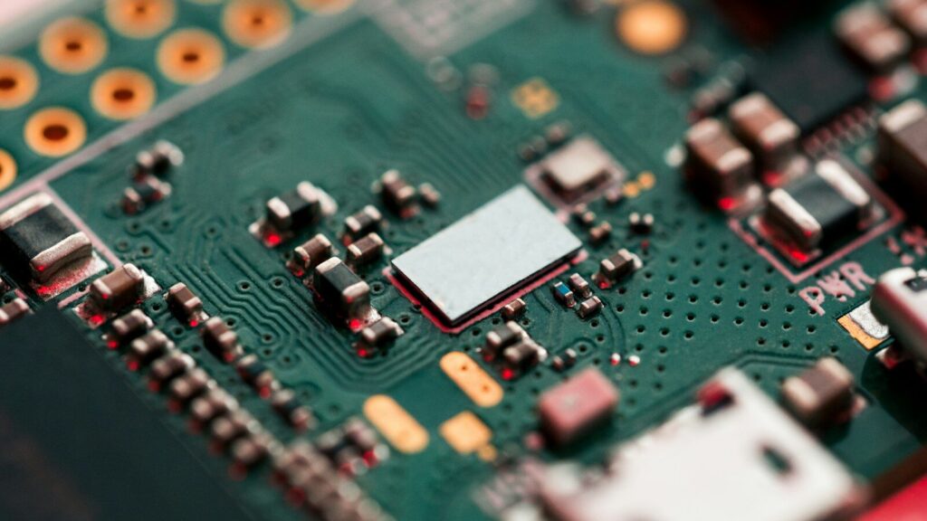
Inside a device, the board does three jobs at once. It connects components electrically, supports them mechanically, and keeps signal behavior predictable enough for the product to pass testing and survive its service life.
Carrying signals and power
Copper traces replace wires. Each trace is a thin strip of copper etched onto an insulating substrate, and a network of traces links component pins. Where a connection has to cross to the other side, a plated hole called a via carries it through.
Power follows a different path. Instead of narrow traces, most designs use large copper areas called planes. A ground plane gives every signal a short return path to its source. A power plane spreads voltage across the board so a chip in one corner sees the same supply as a chip in the other.
Mechanical support and repeatable assembly
The substrate does more than insulate. It holds every component at a coordinate fixed during design, and that is what makes automated assembly possible. Pick-and-place machines drop parts onto solder paste at those coordinates, a reflow oven melts the paste, and the board leaves with hundreds of joints formed in one pass.
| Function | What the board provides | Typical elements |
|---|---|---|
| Electrical connection | Copper paths between components | Traces, pads, vias |
| Power distribution | Stable voltage across the board | Power planes, ground planes |
| Mechanical support | Fixed position for every part | Substrate, solder pads, mounting holes |
| Signal control | Predictable impedance and return paths | Reference planes, controlled-impedance traces |
| Protection | Barrier against moisture and contamination | Solder mask, silkscreen, conformal coating |
Which electronic devices use circuit boards?
Almost every product with a battery or a power cord uses at least one circuit board. The device category usually decides the board structure, the substrate, and how much testing the board has to pass.
Mechanical parts keep giving way to electronic control. A washing machine that once used a timer now runs on a controller board, and a car that once used a distributor now runs on dozens of electronic control units.
Consumer electronics and wearables
Phones, tablets, laptops, smartwatches, and TVs make up the largest share of demand. A single smartphone can hold more than a dozen boards, from the main processor board to small flexible circuits behind the camera. Mid-range main boards run six to ten layers, and flagship models go higher.
Home appliances
Refrigerators, air conditioners, coffee makers, and smart thermostats use simpler boards. Single-sided and double-sided constructions cover most of them because the circuits are modest and cost pressure is high.
Automotive electronics
Modern vehicles carry dozens of control units. Engine controllers, battery management systems, driver-assistance radar and camera modules, and lighting all depend on boards built to survive vibration, temperature swings, and humidity.
Medical devices
Patient monitors, imaging systems, infusion pumps, and portable diagnostic tools need stable analog behavior and long service life. Boards here are also chosen for materials that pass biocompatibility and sterilization requirements.
Industrial and telecom equipment
Programmable logic controllers, motor drives, inverters, and robots work in hot, dusty, electrically noisy environments. Routers, switches, and base stations need controlled impedance and low-loss materials to carry high-speed data without distortion.
| Device group | Typical board need |
|---|---|
| Smartphone | HDI, six to twelve layers, tight layout |
| LED luminaire | Metal-core board for heat spreading |
| Automotive control unit | Vibration and temperature resistance |
| Patient monitor | Stable analog signals, compliant materials |
| Router or radio unit | Controlled impedance, low-loss laminate |
| Industrial controller | Rugged build, long service life |
The most common circuit board applications in electronics
Most boards fall into a few functional roles: signal and control, power conversion, wireless communication, sensing, lighting, and user interface. A single device often contains several of these at once.
Two boards can look similar and behave nothing alike. A board driving a motor draws far more current than a board reading a temperature sensor, and the copper weight, layer count, and thermal design follow from that difference.
Signal and control boards
These boards route logic and control signals in phones, computers, industrial controllers, and embedded modules. The work centers on keeping traces short, keeping return paths continuous, and separating noisy digital sections from sensitive analog ones.
Power conversion boards
Chargers, adapters, inverters, and motor drives carry real current. Traces get wider, copper gets thicker, and heat has to leave the board instead of pooling under a component. Metal-core substrates and heavier copper are common here.
RF and wireless boards
Bluetooth, Wi-Fi, GPS, and cellular radios need traces with a defined impedance, usually 50 ohms, plus materials whose properties stay stable at the operating frequency. Ordinary FR-4 shifts enough above a few gigahertz that the same trace measures differently than it did during printed circuit board design.
Sensor, lighting, and interface boards
Sensor boards sit in wearables, automotive modules, and industrial monitoring gear. Lighting boards back LED arrays and often double as the heat sink. Interface boards handle displays, buttons, and ports, so they take the wear that comes with repeated plugging and pressing.
| Application | Typical products |
|---|---|
| Signal processing | Phones, tablets, computers, controllers |
| Power management | Chargers, adapters, inverters, motor drives |
| Wireless communication | Routers, GPS units, IoT modules |
| Sensing | Smartwatches, industrial meters, radar modules |
| Lighting | LED lamps, automotive lighting, indicators |
| Interface and control | Displays, keypads, HMI panels |
Matching circuit board types to applications
The application sets the minimum requirements, and the board type follows. Simple products use single-sided or double-sided boards, dense products need multilayer or HDI, moving joints need flex or rigid-flex, and high-heat or high-frequency designs need special substrates.
A heavier board than the application needs raises cost and lead time for no gain. A lighter one saves money up front and shows up later as field failures.
Layer count and when it matters
Single-sided boards carry traces on one face and suit basic circuits. Double-sided boards add a second routing layer and a via to link them, and they cover the largest share of production by volume. Multilayer boards stack four or more conductive layers, and the inner layers often serve as power and ground planes.
Rigid, flexible, and rigid-flex
Rigid boards dominate because they are cheap, stable, and easy to assemble. Flexible boards bend and fit where a rigid board cannot reach, such as a hinge in a foldable phone. Rigid-flex boards combine both, keeping rigid sections for components and flexible sections for the connections between them.
Substrates for heat and high frequency
Standard FR-4 handles most designs. When heat is the limit, metal-core boards move it away from the components. When frequency is the limit, low-loss laminates keep the signal intact. Ceramic substrates appear where thermal expansion and temperature extremes matter most.
| Board type | Best fit | Trade-off |
|---|---|---|
| Single-sided | Simple, low-cost circuits | Limited routing, one component side |
| Double-sided | General-purpose products | More routing, still inexpensive |
| Multilayer | Dense digital and mixed-signal designs | Higher cost, longer lead time |
| HDI | Phones, wearables, compact modules | Tighter process control needed |
| Flexible | Moving joints, tight enclosures | Higher material cost |
| Rigid-flex | Products with both needs | Most complex to build |
| Metal-core | LED and power applications | Limited to simpler circuits |
How requirements change by industry
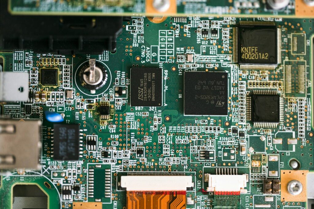
Each industry sets its own bar. Consumer products optimize for cost and size, automotive and industrial products for durability, and medical and aerospace products for reliability with documentation behind it.
A design can be identical on paper and still be built three different ways depending on where it is going. The difference sits in material grades, inspection depth, and the paperwork that travels with each lot.
| Industry | Key requirement | Common board choice |
|---|---|---|
| Consumer electronics | Small size, low cost, fast ramp | HDI, multilayer, rigid-flex |
| Automotive | Vibration and thermal cycling | Multilayer, metal-core for lighting |
| Medical | Signal stability, biocompatible materials | Rigid, rigid-flex, high-reliability builds |
| Aerospace and defense | Weight, radiation, wide temperature range | High-frequency, multilayer, ceramic |
| Industrial | Noise immunity, long service life | Thick copper, conformal coated |
| Telecom | Signal integrity at high frequency | RF, controlled-impedance laminates |
Where standards and qualifications come in
Industry standards give buyers a common language. The IPC design standards cover printed circuit board design and qualification requirements, so a buyer in one country can compare a supplier in another on the same terms. Where safety is at stake, buyers ask for documented compliance rather than a data sheet alone.
How material and design choices show up in real devices
Board material and layout decide whether a product runs cool, keeps its signal clean, and lasts through years of use. The same circuit can pass or fail depending on the substrate, the copper weight, and the trace geometry.
Two devices can use the same chip and deliver different results. A board with a weak ground plane overheats in a thin enclosure, and a board with unmatched traces loses timing margin at high speed.
Substrate selection
FR-4 is the default: glass-fiber cloth bonded with epoxy resin, cheap, strong, and electrically adequate for most products. High-Tg versions hold their shape better when the board sees heat during assembly. Polyimide appears in flexible and high-temperature designs, and low-loss laminates pay for themselves at microwave frequencies.
Trace routing, impedance, and thermal vias
Trace width sets how much current a line can carry, and trace spacing sets how much one line interferes with its neighbor. High-speed interfaces need controlled-impedance routing, typically held within about 10 percent of the target, so the fabricator has to control dielectric thickness and trace width tightly. What separates a workable printed circuit board design from a circuit board design that fails in the field usually comes down to how well those requirements survive the handoff to production.
Heat is handled at the same time. Thermal vias under a hot component carry heat to copper on inner or bottom layers, where it spreads out. A layout that ignores this turns a small hot spot into the failure point that defines the product’s life.
Emerging applications shaping the next generation of boards
New product categories are pushing boards into territory that standard FR-4 was never designed for: foldable displays, electric-vehicle battery management, 5G and 6G radios, edge AI hardware, and grid-scale energy systems.
Three shifts are happening at once. Devices keep shrinking while carrying more functions, so layer counts and feature density rise. Frequencies keep climbing, so material selection matters more than a decade ago. Currents keep growing, so thermal design has moved from an afterthought to a first-order decision.
How to choose the right circuit board for a device
Start from the application, not the board. Define the environment, the signal speeds, the thermal load, and the expected service life, then let those requirements set the layer count, substrate, and finish.
- List the operating conditions: temperature range, humidity, vibration, and any chemical exposure.
- Estimate the highest signal frequency and the maximum current each section has to carry.
- Decide the layer count and stack-up from routing density and the need for reference planes.
- Pick the substrate and surface finish from the frequency and thermal findings.
- Confirm the assembly and test plan, including the inspection level and any required documentation.
- Check that the supplier can hold the tolerances the design needs, not just build the board.
At the prototype stage these choices are cheap to change. At volume they are not, which is why printed circuit board manufacturers who offer faster PCB assembly and answer questions before release to production tend to save more time than a lower unit price. Buyers comparing printed circuit board assembly suppliers usually weigh engineering support alongside fabrication cost.
FAQ
What is the difference between a PCB and a PCBA?
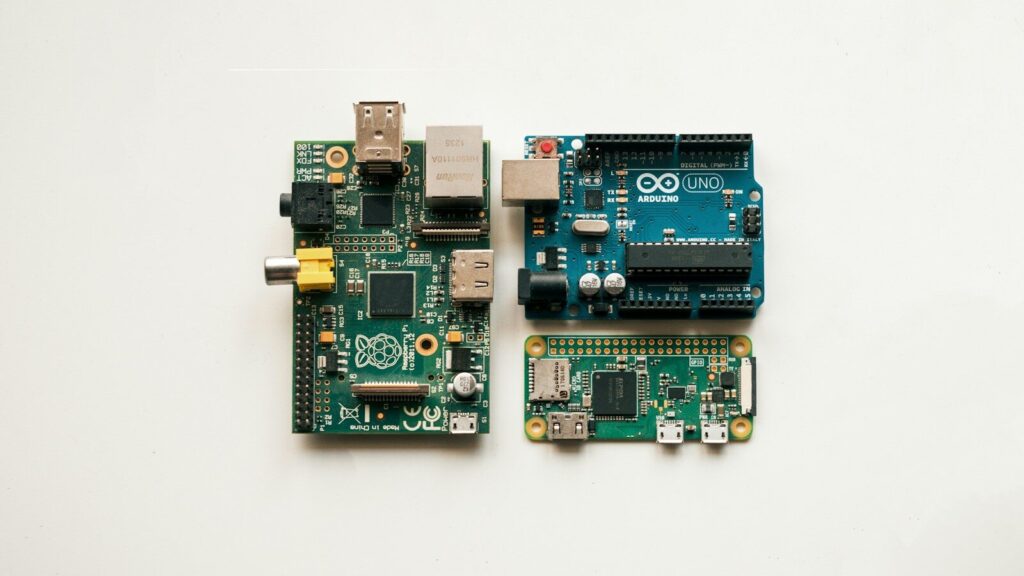
A PCB is the bare board: substrate, copper traces, solder mask, and silkscreen, with no components attached. A PCBA is that same board after components have been soldered onto it.
Are circuit boards the same in every device?
No. A board for an LED lamp may have one conductive layer and no components beyond the LEDs, while a phone mainboard can carry twelve layers and hundreds of parts. Size, thermal load, frequency, and expected life drive the difference.
Can a circuit board be repaired instead of replaced?
Sometimes. Failed components, cracked solder joints, and damaged connectors can often be replaced, and cleaning can restore boards affected by flux residue. Damage inside the board itself, such as a burned internal layer or a lifted pad, usually cannot be repaired reliably, so the board is replaced.


