
Every electronic product sits on a substrate most buyers never inspect. When a board fails in the field, or a quote comes back above target cost, the cause often traces to the laminate under the copper. That is why sourcing teams and engineers search for what PCB boards are made of: the substrate sets the ceiling on heat tolerance, signal loss, and service life before a single component is placed.
A circuit board material is the non-conductive substrate that supports and insulates the copper traces on a printed circuit board (PCB). In most designs it is woven glass fiber bonded with epoxy resin, supplied as a copper-clad laminate in standard thicknesses and flame ratings. That one choice fixes the board’s thermal limit, dielectric loss, stiffness, and unit cost.
What follows covers the material types in use, the properties that drive selection, and how to match a laminate to an application.
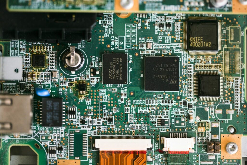
What is a circuit board material?
A circuit board material is the insulating core of a PCB, not the finished board. It ships as a copper-clad laminate, meaning copper foil is already bonded to one or both faces and the sheet is ready for imaging, etching, and drilling.
The circuit board material name printed on a fabrication drawing, such as FR-4, points to a family of formulations rather than one product. Two laminates can share the FR-4 label and still differ in resin chemistry, glass weave, and glass transition temperature. A drawing that says only FR-4 leaves the fabricator room to choose, which is why buyers who need consistency name a specification sheet.
The layer stack of a printed circuit board
| Layer | Typical material | Function |
|---|---|---|
| Substrate | Woven glass fiber with epoxy resin | Mechanical support and electrical insulation |
| Copper | Electrodeposited copper foil, 0.5 to 4 oz | Carries signals and power |
| Solder mask | Photoimageable epoxy-based polymer | Protects traces, prevents solder bridging |
| Silkscreen | Cured epoxy ink | Reference designators and test points |
Only the substrate is strictly the printed circuit board material. Copper weight and mask chemistry still affect current capacity and surface insulation.
Circuit board material types
FR-4 is the default circuit board material for most applications. Alternatives exist for four reasons: lower cost, higher heat, flexibility, and lower signal loss at high frequency.
Roughly nine boards in ten use a glass-reinforced epoxy laminate. The rest splits across paper-based laminates for disposable electronics, polyimide for flexible and high-temperature work, metal-core and ceramic substrates for power, and PTFE for radio frequency designs.
| Material | Reinforcement and resin | Typical Tg (°C) | Dk at 1 GHz | Relative cost | Where it fits |
|---|---|---|---|---|---|
| FR-1 and FR-2 | Paper with phenolic resin | 105 to 130 | 4.5 to 5.0 | Lowest | Single-sided consumer goods |
| CEM-1 | Paper core with glass surface | 105 to 115 | 4.5 to 5.0 | Low | Single-sided boards in humid use |
| CEM-3 | Non-woven glass with epoxy | 110 to 130 | 4.0 to 4.5 | Low | Simple double-sided boards |
| Standard FR-4 | Woven glass with epoxy | 130 to 140 | 4.2 to 4.8 | Baseline | General electronics, multilayer logic |
| High-Tg FR-4 | Woven glass, modified epoxy | 170 to 180 | 4.0 to 4.7 | Moderate | Lead-free assembly, automotive |
| Polyimide | Glass or aramid with polyimide | Above 250 | 3.2 to 3.6 | High | Flex and rigid-flex aerospace |
| Aluminum core | Aluminum base with dielectric | Not applicable | 3.5 to 4.5 | Moderate | LED lighting, power electronics |
| Ceramic | Alumina, or aluminum nitride | Not applicable | 5.7 to 9.8 | High | High-power RF, extreme heat |
| PTFE | PTFE with glass or ceramic filler | Not applicable | 2.0 to 2.6 | Highest | Millimeter wave, radar, satellite |
Rigid laminate substrates
Paper-based laminates sit at the bottom of the cost ladder. They punch cleanly, accept tin-lead wave soldering, and cannot support plated through-holes, which confines them to single-sided boards. CEM-1 and CEM-3 add a glass surface layer or a non-woven glass core, improving moisture resistance and allowing simple double-sided construction. Standard FR-4 covers the middle of the market. Its glass transition temperature of 130 to 140 °C suits tin-lead assembly, but lead-free reflow peaks near 260 °C, so boards passing through multiple reflow cycles usually move up to a high-Tg grade.
Flexible and rigid-flex substrates
Polyimide replaces the rigid glass-epoxy core with a film that bends without cracking and tolerates sustained temperatures above 250°C. Flex circuits handle dynamic bending in wearables and camera modules, connect rigid sections inside one stack-up, and cut connector count in compact assemblies. The trade-off is price: polyimide costs several times more than FR-4 and needs different drilling parameters.
Metal-core and ceramic substrates
When heat cannot leave through the components, it has to leave through the board. An aluminum or copper core spreads heat far faster than any glass-epoxy laminate, with effective thermal conductivity from 1.0 to 4.0 W/(m·K). A ceramic PCB substrate goes further, reaching 20 to 180 W/(m·K) while holding a low coefficient of thermal expansion.
High-frequency laminates
Standard FR-4 works well up to roughly 2 to 3 Gbps of serial data. Beyond that, dissipation turns into measurable attenuation, and impedance control becomes sensitive to resin variation. PTFE and hydrocarbon ceramic laminates push dielectric constant down to 2.0 to 2.6 and dissipation factor below 0.002, which is why millimeter-wave and radar designs specify them. Hybrid stack-ups, using the low-loss laminate only on critical layers, keep costs under control.
Key circuit board material properties
Eight numbers decide whether a laminate fits a design: glass transition temperature, decomposition temperature, coefficient of thermal expansion, dielectric constant, dissipation factor, thermal conductivity, water absorption, and density.
Two laminates can carry the same grade label and still differ enough on these points to change the outcome of a thermal cycle test. The ranges below describe a standard general-purpose glass-epoxy laminate.
| Property | Typical value | Test basis |
|---|---|---|
| Density | 1.8 to 2.0 g/cm³ | ASTM D792 |
| Glass transition temperature | 130 to 140°C | IPC-TM-650 2.4.25 |
| Decomposition temperature | 300 to 340°C | IPC-TM-650 2.4.24 |
| Dielectric constant at 1 MHz | 4.2 to 4.8 | IPC-TM-650 2.5.5 |
| Dissipation factor at 1 MHz | 0.015 to 0.025 | IPC-TM-650 2.5.5 |
| CTE, z-axis below Tg | 50 to 70 ppm/°C | IPC-TM-650 2.4.41 |
| Thermal conductivity | 0.25 to 0.35 W/(m·K) | ASTM E1530 |
| Water absorption, 24 hours | 0.10 to 0.20 percent | ASTM D570 |
| Flexural strength, lengthwise | 415 to 550 MPa | ASTM D790 |
These figures are not vendor claims. They trace back to the test methods published in IPC-4101, the specification for base materials for rigid and multilayer printed boards, which sets ceiling values for dielectric loss, decomposition temperature, and flammability across dozens of specification sheets. Citing the base standard alone tells the fabricator very little.
Thermal properties
The glass transition temperature marks where the resin stops behaving as a rigid solid and starts expanding faster. Below Tg, a standard laminate expands about 50 to 70 ppm/°C through its thickness; above Tg, that figure can more than double. The copper barrel of a plated via expands at roughly 17 ppm/°C, so repeated excursions above Tg stress the barrel and eventually crack it near the knee.
Electrical properties
Dielectric constant sets trace geometry for a target impedance, so a stack-up calculated with Dk 4.3 behaves differently from one built with Dk 4.0. The dissipation factor sets how much signal energy converts to heat per unit length, and that loss grows with frequency. Tracking index matters wherever mains voltage sits near the surface, since a low index forces wider creepage spacing.
Mechanical and physical properties
Circuit board material density sits between 1.8 and 2.0 g/cm³ for glass-epoxy laminates, with higher glass content pushing toward the top of the range. Density rarely decides a design alone, but it feeds weight budgets for handheld and airborne products. Flexural strength, water absorption, and thermal expansion together predict behavior under vibration, humidity, and cycling.
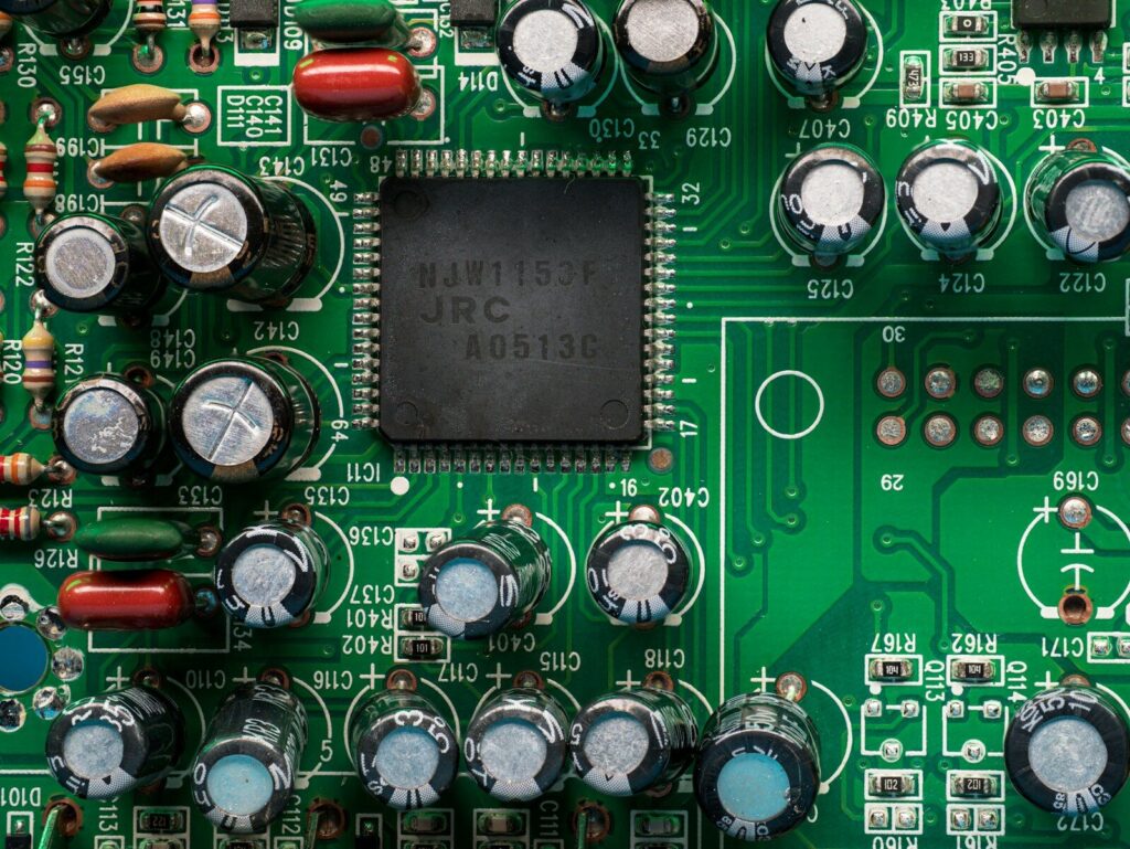
How circuit board material affects PCB design and performance
Material choice determines whether impedance can be controlled reliably, whether heat can leave the assembly, and whether the board survives reflow without delaminating.
Signal integrity
Trace width for a 50-ohm microstrip depends on the dielectric constant of the laminate beneath it, and the loss budget depends on the dissipation factor. That is why printed circuit board design review starts with the stack-up: on high-speed links, a low-loss laminate often buys more margin than tighter routing rules.
Thermal management
A laminate with low thermal conductivity forces the design to compensate through thermal vias, copper pours, and component spacing. Power boards usually push heat down through the substrate into a metal core or heatsink, so substrate thermal conductivity enters the conversation before layer count is fixed.
Assembly and manufacturability
Every material has to survive the soldering profile. Lead-free reflow peaks at 260 °C, and multiple passes multiply the thermal load on the resin. Materials that punch rather than drill save time at volume but rule out plated through-holes, so the laminate and the assembly method belong in one discussion.
How to choose a circuit board material
Work from the requirements inward: define the thermal and signal envelope first, then mechanical needs, then compliance, and compare cost last.
- Set the maximum continuous operating temperature and the soldering profile, including rework cycles.
- Estimate the fastest signal rate and decide whether controlled impedance or a loss budget applies.
- Note mechanical requirements such as bend radius, connector stiffness, weight limits, and hole counts.
- Confirm compliance obligations, including halogen content, flammability rating, and tracking index.
- Compare laminate cost against yield, layer count, and assembly method rather than in isolation.
A material that looks cheaper on paper can raise total cost if it forces extra layers, wider spacing, or a slower drilling process.
Is circuit board material hazardous?
No. FR-4 is woven glass fiber bonded with epoxy resin. It contains no asbestos, and an undamaged finished board is safe to handle with bare hands.
The comparison persists because early boards used paper-phenolic cores that look fibrous when they break and because asbestos was once common in unrelated electrical insulation. The real precautions concern processing. Cutting, routing, and sanding glass-epoxy generate fine dust that irritates lungs and skin, so extraction and protective equipment belong on any fabrication line. Older boards may carry lead solder or brominated flame retardants.
Circuit board material in 3D formats
A 3D circuit carrier replaces the flat laminate with a molded plastic part, so the substrate, the wiring, and the housing become one component.
Interest in 3D circuit board material comes from two directions. The established route is laser direct structuring, used for phone antennas and sensor carriers: a thermoplastic is compounded with a laser-activatable additive, injection molded into its final shape, then traced by a laser that exposes metal seeds along the circuit path. Electroless copper plating builds conductors only where the laser has activated the surface, and components are soldered afterward. Conductive filaments for additive manufacturing follow the same idea in prototype form, but they carry much higher resistance.
From prototype to production: material choices at each stage
Prototypes can trade performance for speed. Production cannot, because every material decision is locked into tooling, panel sizes, and qualification records.
What is the cheapest PCB material?
Paper-phenolic laminates such as FR-1 and FR-2 cost the least, with CEM-1 next and CEM-3 above it; a paper-based board runs at a fraction of the cost of an equivalent FR-4 panel. The saving is real but narrow. These materials are limited to single-sided boards, cannot take plated through-holes, and delaminate under lead-free reflow, so they suit remote controls, basic adapters, and similar high-volume products with a short service life.
Can I make my own circuit board?
Yes, within limits. Single-sided paper-based laminate can be milled or etched at a bench without specialized equipment, and it poses far less dust hazard than glass-epoxy. Milling FR-4 at home is different: the glass content produces abrasive, irritant dust and dulls tooling quickly. For anything beyond a simple single-sided circuit, ordering fabricated boards is faster and cheaper than building them, and it avoids the reliability problems of hand-applied plating.
Sourcing circuit board material for volume production
Volume production depends on naming the material precisely, not on naming the grade family.
A workable fabrication note combines three elements: the base standard, the specific specification sheet, and any requirement that the sheet does not cover, such as a minimum glass transition temperature. Vague wording such as “or equivalent” invites substitution, and a board that passes incoming inspection can still fail thermal cycling months later. Buyers working with printed circuit board manufacturers should also confirm surface finish, copper weight, and panel utilization, because those move costs as much as the laminate. Where a program spans fabrication and printed circuit board assembly, one supplier accountable for the material specification removes the argument about where a fault originated.
FAQ
What standard thicknesses are available for circuit board material?
Copper-clad laminate is stocked from roughly 0.8 mm to 2.0 mm for common boards, with 1.6 mm as the default, and thicker panels up to about 6.35 mm. Tolerances tighten to around plus or minus 10 percent where impedance is controlled, because layer spacing shifts trace impedance.
Can circuit board material be recycled or reused?
Glass-epoxy laminate is hard to separate into usable resin and fiber, so most of it is shredded, burned for energy recovery, or landfilled, while metal content is recovered separately. The practical lever is design: fewer layers, better panel utilization, and longer product life cut the volume reaching end-of-life processing.
How does circuit board material behave in humid environments?
Glass-epoxy absorbs roughly 0.10 to 0.20 percent moisture by weight after 24 hours of immersion, and paper-based laminates absorb several times more. Absorbed moisture lowers insulation resistance and expands during soldering, which is why boards are baked before reflow.


