Ask five engineers how many types of PCB there are and you get two different answers, and both are right. One group counts copper layers. The other counts what the board is made of. That confusion costs money at the buying stage, because a request that says only “advanced PCB” or “4-layer board” leaves the substrate open, and the substrate is where the mechanical behaviour and most of the cost live. If you are sourcing a flexible PCB for the first time, the gap between those two answers is where most quoting delays start.
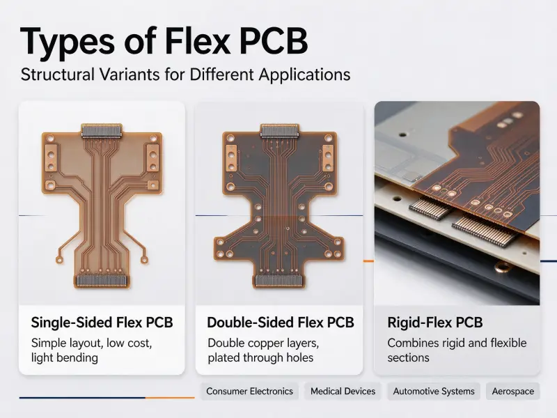
The three types of PCB are rigid, flexible and rigid-flex, and they are sorted by the base material the circuit sits on. A rigid PCB holds its shape on a stiff substrate such as FR-4. A flexible PCB bends, because it is built on a thin polyimide film. A rigid-flex board puts both into one part, with stiff sections for components and flexible sections that fold. There is a second set of three, single-sided, double-sided and multilayer, which counts copper layers instead, and it runs across the first set rather than competing with it.
The sections below cover each type, what a flexible PCB supplier custom FPC needs from your drawing, and how to decide which one you actually need.
What are the three types of PCBs?
They are rigid, flexible and rigid-flex, grouped by substrate. The rigid board is the default for flat assemblies that carry a lot of parts. The flexible board is the answer when the circuit has to move, fold or fit a space no rigid board will enter. The rigid-flex board does both jobs in a single part, at a higher unit cost.
Rigid PCBs
A rigid PCB is built on a glass-reinforced epoxy laminate, most often FR-4. It keeps its shape after lamination, which is what lets it carry heavy parts, connectors and heat sinks without extra support. Standard thickness sits near 1.6 mm, and the same construction scales from one copper layer to twenty or more. It is also the cheapest way to get a flat, dense layout into volume production.
Flexible PCBs
A flexible PCB board trades the stiff laminate for a polyimide film, usually 25 µm or 50 µm thick, with copper bonded to it. It bends, folds and twists, and it can stand in for a cable, a connector, or both at once. Finished thickness runs from roughly 0.07 mm for a single-layer build to around 0.25 mm for a four-layer one. That thinness is the whole point.
Rigid-flex PCBs
A rigid-flex board laminates rigid and flexible sections into one structure, so the copper runs through both with no connector in between. Components live on the rigid areas and the flexible areas fold the assembly into its final shape. It is the most complex of the three to build. A rigid-flex PCB manufacturer supplier will normally ask where the fold sits, what angle it takes and how many times it moves, because those answers set the material stack.
The other three: by copper layer count
Sort the same boards by copper layers and a second list of three appears. A single-sided PCB has copper on one face only, so traces cannot cross and the layout has to route around them. A double-sided PCB has copper on both faces joined by plated through holes, which roughly doubles the routing area and frees one face to work as a ground plane. A multilayer PCB presses three or more copper layers together with insulating prepreg between them, and past four layers it is usually built with an even count to keep the stack symmetrical.
Why one name is never enough on a quote request
The two lists are independent. A four-layer board can be rigid, and a flexible circuit can be single-sided, which is why a request for a “6-layer PCB” is not finished. It says nothing about the substrate, and the substrate decides the bend capability, the material set and most of the process steps. Early in the PCB learning curve, this two-axis framing is the fastest way to read any board specification someone hands you.
| Rigid PCB | Flexible PCB | Rigid-flex PCB | |
| Base material | Glass-reinforced epoxy, usually FR-4 | Polyimide film | Both, laminated in one part |
| Conductor | Electrodeposited copper | Rolled annealed copper in bend areas | Both, chosen by section |
| Typical thickness | Around 1.6 mm | Roughly 0.07 mm to 0.25 mm | Varies by section |
| Bend capability | None | Bends, folds, dynamic flexing | Folds at the flexible sections |
| Stiffeners | Not needed | Needed under connectors and parts | Rigid sections do the job |
| Typical applications | Motherboards, power supplies, industrial controllers | Camera modules, wearables, LED strips, printer heads | Drones, medical probes, automotive sensor modules |
| Main design risk | Wrong layer count for the job | Bend radius below the minimum | Stress at the rigid-to-flex transition |
What is a flexible PCB made of?
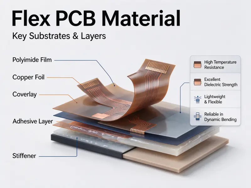
A flexible PCB is a polyimide film with copper bonded to it, a polyimide coverlay over the copper in place of liquid solder mask, and stiffener sheets wherever a connector or a component needs a flat, hard surface. Adhesive-based or adhesiveless bonding holds the copper to the film.
Flexible PCB material: polyimide film and the adhesive question
Polyimide is the base of nearly every flexible PCB material system. It survives reflow temperatures and stays flexible across a wide temperature range. Copper can be bonded to it with an acrylic or epoxy adhesive, or bonded directly in an adhesiveless construction. Adhesiveless laminates cost more, but they come out thinner, hold dimension better and survive dynamic flexing far longer.
Rolled annealed copper versus electrodeposited copper
Copper type matters more here than on rigid boards. Rolled annealed copper has an elongated grain structure that tolerates repeated bending. Electrodeposited copper has a more vertical grain that cracks sooner under the same motion, although it is cheaper and fine for static installations. Calling out electrodeposited copper inside a bend zone is one of the more common flex failures, and one of the easier ones to avoid on the drawing.
Coverlay and stiffeners take the place of solder mask
Coverlay is a polyimide film with adhesive, laminated over the etched copper. It does what solder mask does on a rigid board, and it also has to survive the bending. Openings are cut rather than imaged, so registration is looser, and opening each pad by roughly 0.1 mm to 0.2 mm per side is normal practice. Stiffeners, in polyimide, FR-4 or stainless steel, go under connector fingers and heavy parts.
Flexible PCB thickness, layer by layer
Flexible PCB thickness is the sum of the stack: base film, copper on each face, coverlay on each face, plus any stiffener. A single-layer dynamic hinge build, 25 µm film, 18 µm rolled annealed copper and 25 µm coverlay, lands near 0.07 mm. A two-layer build with 18 µm copper on a 25 µm core and coverlay both sides comes to roughly 0.12 mm. Four layers pushes past 0.20 mm, and at that point the board belongs in a static bend rather than a moving hinge.
None of this is invented project by project. The base dielectric, the coverlay and the finished board each have their own IPC documents, and finished flexible and rigid-flex boards are qualified against IPC-6013, which covers single-sided, double-sided, multilayer and rigid-flex multilayer constructions including stiffeners, plated through holes, microvias and blind or buried vias (IPC-6013D, ipc.org).
| Document | What it covers |
| IPC-2221 | Generic design requirements for printed boards |
| IPC-2223 | Sectional design standard for flexible and rigid-flex boards |
| IPC-4203 | Coverlay and bonding films |
| IPC-4204 | Flexible copper-clad dielectric materials |
| IPC-6013 | Qualification and performance of finished flexible and rigid-flex boards |
| IPC-A-600 | Visual acceptance criteria |
What design rules keep a flexible PCB from cracking?
Bend radius is the one that matters most. It is written as a multiple of the finished thickness of the flex section, and going under it does not break the board on the bench. It cracks the copper months later, in the field, at the fold.
Bend radius is a multiple of thickness
Ratios quoted against IPC-2223 vary a little between published sources, and the honest range looks like this. For a static bend-to-install, single-sided flex is often quoted near 6 times the thickness, double-sided near 10 to 12 times, and multilayer around 12 to 20 times. Dynamic flexing, where the part moves in service, starts well above that, and high-cycle designs are quoted at 100 times or more. Confirm the figure with your fabricator, because the real number depends on copper type, copper weight, layer count and how often the part moves.
What stays out of the bend area
Vias, pads and component bodies do not belong in a bend zone. Vias are stress concentrators and turn into crack initiation points. Traces should run perpendicular to the bend axis, corners should be rounded, and trace width is often increased through the bend. The stiffener edge should sit clear of the bend tangent, about 1 mm minimum and closer to 2 mm where the part moves.
Planes, copper balance and hatched fills
A solid copper plane makes a flex section stiff. Where a ground or power plane is needed in a flexible area, a hatched pattern keeps most of the electrical benefit while leaving the bend possible. Copper also needs to be balanced across the stack, because an unbalanced build curls during lamination. In pcb board design terms, the bend area is a mechanical zone first and an electrical one second.
Connector zones and stiffener placement
ZIF and board-to-board connectors need a hard, flat landing area, which is what the stiffener provides. Polyimide stiffeners keep some flexibility and run about 0.05 mm to 0.25 mm. FR-4 stiffeners give real rigidity at roughly 0.2 mm to 1.6 mm, and stainless steel sits at about 0.1 mm to 0.3 mm where dimensional stability matters most. Match the stiffener to the flexible PCB connector you are mating with, not to whatever the last design used.
What are some examples of PCBs in real products?
Rigid boards show up wherever the assembly is flat and stays put. A flexible PCB shows up wherever the circuit has to move, fold or fit a thin space. Rigid-flex shows up where both are true in the same part.
Rigid board examples
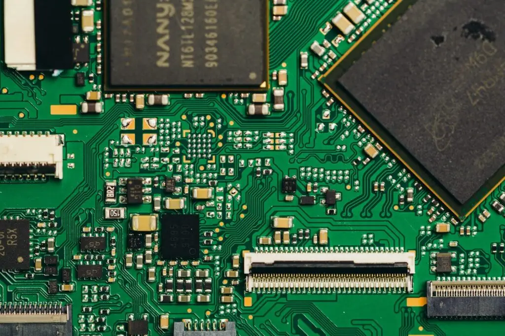
Desktop and server motherboards, power supplies, industrial controllers, appliance control boards and LED drivers are all rigid FR-4 boards. Each one is a pcb circuit that sits flat, carries parts of real weight, and asks nothing of the enclosure.
Flexible PCB examples
The ribbon between a phone camera module and the main board is a flexible PCB board. So are laptop lid hinge cables, printer head cables, earbud and watch internals, LED strip sections, membrane keypad tails and disposable medical sensors. In nearly every case the flex circuit is standing in for a wire, a connector, or both.
Rigid-flex examples
Drones use rigid-flex where the flight controller and the camera need to be one part. Medical endoscopes and probes use it because there is no room for a connector and no tolerance for one failing. Automotive sensor modules and avionics boxes use it for the same reason: fewer mating interfaces means fewer things to shake loose.
How do you choose between rigid, flexible and rigid-flex?
Start with the mechanics, not the circuit. If nothing moves and the enclosure is flat, rigid wins on cost. If the circuit has to bend in service, flex is the answer. If it has to carry components and fold once into place, rigid-flex usually beats a rigid board plus a cable.
Five questions before you pick a type
Does any part of the circuit move after assembly? How many components sit on it, and how heavy are they? How many routing layers does the schematic need? What does the environment do, in terms of vibration, temperature cycling and moisture? And what is the production volume, because tooling and engineering effort spread across volume and hurt badly on a one-off prototype?
When a flexible PCB replaces a cable
Every board-to-board connector is two mating interfaces, at least two assembly steps, and a failure point under vibration. A flex circuit removes all of it. That is usually the first reason a design moves off rigid boards, and it is why a single-sided flex can come out cheaper than the harness it replaces once assembly labour is counted.
When rigid-flex is cheaper than the assembly it replaces
Per board, rigid-flex costs more than a rigid board plus a cable. At the assembly level it often costs less, because the connectors, the cable, the extra soldering operations and the failure modes all go away. The trade favours rigid-flex where reliability matters and volume is modest. It usually does not favour it in cost-driven consumer products.
| Your constraint | Start with | Because |
| Flat, static, cost sensitive | Rigid FR-4, single or double sided | Fewest process steps |
| Controlled impedance or several power domains | Rigid multilayer | Dedicated planes and defined return paths |
| Folds once at assembly | Single or double-sided flex | Cheaper than a connector and cable pair |
| Moves in service | Flex with rolled annealed copper | Electrodeposited copper cracks under repeated bending |
| Components plus a reliable fold | Rigid-flex | Removes the mating interface |
| Tight space, no room for a connector | Rigid-flex | One part instead of three |
What drives the PCB price for each type?
Price follows the number of process steps and the amount of panel each board wastes, not the name on the drawing. A single-sided flexible board and a single-sided rigid board can land close together. A six-layer rigid-flex board sits in a different band entirely.
Process steps, not the label
Every extra lamination, drill cycle, plating step and registration check adds cost, and the steps stack. Going from two layers to four is usually a smaller jump than moving from through-hole vias to blind or microvia construction, because the latter needs sequential lamination. Non-recurring engineering, tooling, test fixtures and first-article inspection, is billed separately from unit price.
What moves flexible PCB price
On the flex side the drivers are layer count, copper type and weight, adhesiveless versus adhesive-based laminate, coverlay opening accuracy, stiffener material and count, panel utilisation, and how much electrical testing you specify. Fine trace and space pushes yield down. So does asking for a tight bend radius on a stack that is already thick.
What to send with an RFQ
Send the Gerbers, the target stack-up, the bend locations with angles and cycle counts, the performance class, the volume, and any compliance requirements. That is what a flexible PCB manufacturer needs to return a quote you can compare against another one. In pcb manufacturing, a request that only says “flex circuit, 2 layer” will come back as a number, but not as a comparable number, and the pcb price will move the moment the missing details arrive.
| Cost driver | What changes |
| Layer count | Lamination, drilling and registration cycles |
| Via type | Through-hole versus blind, buried or microvia |
| Base material | FR-4, polyimide, adhesiveless laminate |
| Copper type and weight | Rolled annealed versus electrodeposited; 12 µm to 70 µm |
| Minimum trace and space | Etch yield and inspection time |
| Stiffeners and coverlay | Extra material and extra lamination steps |
| Test coverage | Flying probe versus fixture, full electrical test |
| Volume and panel use | Where the non-recurring engineering is spread |
FAQ
Is a flexible PCB always more expensive than a rigid board?
Not always, although at equal layer count the bare board usually is. Polyimide film and rolled annealed copper cost more than FR-4 and standard foil, and the process is less forgiving. The comparison has to be made at assembly level, though. If one flex tail removes a connector, a cable and two soldering operations, the total can come out lower. Ask for both numbers before you decide.
Can a flexible PCB replace the wiring harness inside a product?
Often, and that is one of the main reasons to use one. A flex circuit gives repeatable routing, defined geometry and a part that drops into assembly in a single motion instead of being dressed and tied by hand. It stops being the right answer when the run is long and electrically trivial, when it has to carry real current, or when the harness needs re-routing late in the build.
Which of the three types gets used most often?
The rigid FR-4 board, most often in two or four layers. It covers the widest range of products at a cost volume production can absorb, and it needs the least design support from the fabricator. Flexible and rigid-flex boards get chosen when a specific mechanical or reliability constraint rules rigid out, not as a general upgrade over it.