
Modern electronics keep shrinking while packing more functions. Designers face a real problem: fitting rigid boards, connectors, and cables into tight, oddly shaped enclosures without adding weight or failure points. A rigid-flex PCB manufacturer supplier can build these hybrids to match a specific enclosure, but understanding the board type itself comes first.
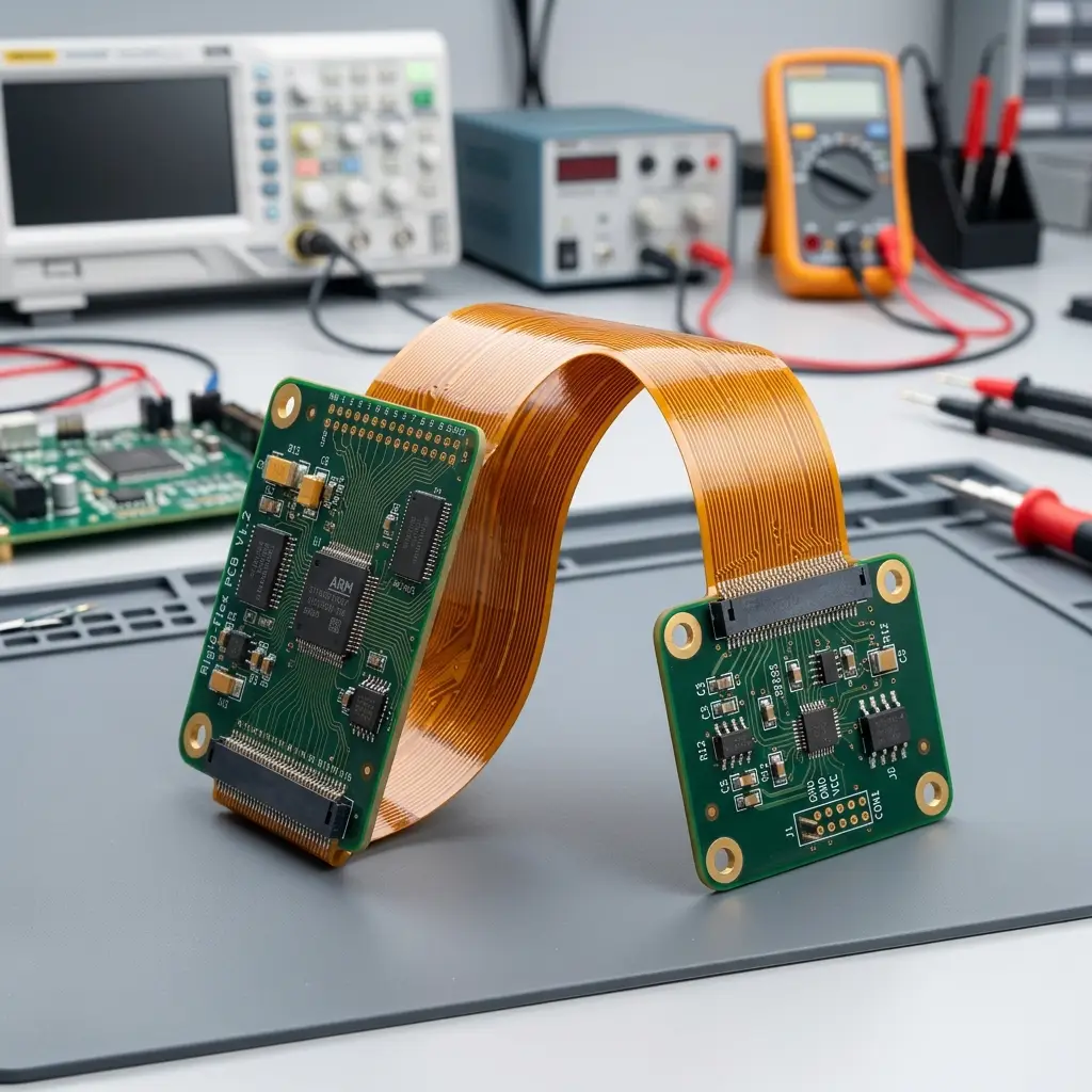
A rigid-flex PCB is a single printed circuit board that combines rigid sections and flexible sections into one interconnect structure. The flexible portions bend or fold to connect rigid boards, while the rigid portions carry components and hold the shape. This hybrid construction removes many connectors and cables, saves space and weight, and lets a product be assembled in three dimensions instead of a flat plane.
The sections below walk through how these boards are built, how they compare with other PCB types, and what drives their design and cost.

What is a rigid-flex PCB
A rigid-flex PCB is one board made of bonded rigid and flexible layers that work as a single circuit, letting designers route signals through bends instead of linking separate boards and connectors.
A rigid-flex board starts as a stack of rigid and flexible substrates laminated together. The rigid areas hold the components you would find on a normal board. The flexible areas do the interconnection, bending to reach around corners or folding flat during assembly.
How a rigid-flex board is built
The flexible layers sit buried inside the stack and pass through the rigid sections. Holes drilled and plated through both material types create the electrical paths between them. Copper is imaged and etched to form the circuit pattern, then a coverlay or flexible solder mask protects the exposed flex. Stiffeners can be added under connectors or component spots to keep those areas from bending.
The result is a single part number instead of a rigid board plus a flex cable plus a connector. That consolidation is the core reason teams choose the type when space and reliability matter.
Using a separate rigid board with an external flex cable leaves two part numbers, two solder operations, and a connector that can loosen. Folding the same function into one rigid-flex part removes those handoffs. The trade is a harder design and a higher board price, which the next sections explain.
How rigid-flex PCBs differ from flex and rigid boards
A rigid-flex PCB keeps rigid, component-bearing zones and adds flexible zones only where bending is needed, while a pure flex PCB bends everywhere and a rigid PCB cannot bend at all.
Flex PCB vs. rigid-flex PCB
A flex PCB is flexible across its whole body. It can roll or fold repeatedly and works well for hinges and moving parts. A rigid-flex PCB is flexible only in defined sections. The rigid zones give it flat, stable mounting surfaces and better protection for soldered parts. For products that need some bending but also need solid boards to hold chips and connectors, rigid-flex is the practical middle ground.
Rigid PCB vs. rigid-flex PCB
A rigid PCB is a flat, unyielding board. It is the cheapest and easiest to make, but it cannot follow a curved enclosure. When a design needs to wrap around a battery or stack in three dimensions, a rigid board forces the use of cables and connectors. A rigid-flex PCB removes that step by building the bend into the board itself.
Most designs still use rigid boards where they can. Rigid-flex is chosen when the space, weight, or reliability gain justifies the extra process cost.
A simple way to decide: if the board never moves and fits flat, a rigid PCB wins on cost. If the whole assembly must flex in use, a flex PCB fits. Rigid-flex is the choice when only part of the product bends but the rest needs a stable, component-ready surface.
Rigid-flex PCB materials
Rigid-flex PCBs pair a flexible substrate such as polyimide with a rigid substrate such as FR-4, then bond them with copper foil, adhesive, and a coverlay.
Flexible substrate materials
The flexible part is usually polyimide film, a high-temperature stable plastic that bends without cracking. Polyester, or PET, appears in lower-cost flex that does not need high heat resistance. The choice depends on the bend cycle count and the assembly temperature the board must survive. Polyimide also resists most chemicals used in assembly, which keeps the flex intact through cleaning and soldering. PET suits one-time or low-cycle bends where the board is folded during install and then held still.
Rigid substrate materials
The rigid sections commonly use FR-4, a glass-reinforced epoxy. When signal speed or loss matters, designers turn to high-frequency laminates built for controlled impedance. Mixing a premium laminate in one zone with standard FR-4 in another is one way rigid-flex controls both performance and cost within a single board. The flexible zone rarely needs that premium material, so cost stays focused where the signal actually travels.
Conductive and bonding layers
Copper foil carries the traces. Rolled-annealed copper is preferred in dynamic flex zones because it tolerates repeated bending better than electrolytic copper. Adhesive layers bond the stack, and a coverlay, a flexible version of solder mask, shields the conductors. Stiffeners add local rigidity where connectors or heavy parts sit. Adhesiveless constructions are common in dynamic flex because they resist fatigue better than glued film, though they cost more to produce.
Rigid-flex PCB stackup and construction
A rigid-flex stackup stacks and bonds rigid and flexible layers in a symmetric order so the finished board bends where intended and stays flat elsewhere.
Layer arrangement and symmetry
Engineers place the flexible layers so they run through the rigid blocks and exit where the board must bend. The stack should be symmetric around its center to avoid warpage after lamination. Too many layers in the flex zone make bending harder, so extra routing is usually pushed into the rigid areas. Designers also keep copper balanced on both sides of the center plane so the board does not curl after it leaves the press.
Coverlay and stiffeners
The coverlay protects flex conductors from moisture and abrasion. Stiffeners, made of FR-4 or aluminum, back up zones that carry connectors or components so those spots do not flex. Defining the stiffener location and the flex opening on the drawing prevents confusion at the factory and reduces rejects. A poorly marked transition is a frequent cause of prototypes that bend in the wrong place.
Rigid-flex PCB design guidelines
Rigid-flex design follows IPC-2223 rules for bend radius, keeps vias and pads out of bend zones, and manages the rigid-to-flex transition to protect both signal and structure.
Bend radius rules under IPC-2223
The bend radius must scale with the total thickness of the flex section. IPC-2223 sets the minimum radius as a multiple of that thickness. A single-layer static bend may use about 6 times the flex thickness, while a dynamic bend that flexes for life can need 100 times or more. Measure the radius from the inside of the bend and add margin for material variation and handling. As a rule, a two-layer static flex about 0.2 mm thick needs roughly a 2.4 mm radius, while the same stack in a dynamic application needs closer to 20 mm or more.
Routing and via placement in bend zones
Traces should cross the bend line at roughly 90 degrees and use smooth curves instead of sharp corners. Vias and pads are stress points, so they stay out of active bend areas. Where conductors stack on opposite layers, stagger them to avoid a stiff beam effect that concentrates stress and cracks copper under movement. Smooth, gradual trace width changes also help the copper survive the bend without thinning at the edges.
Transition zones and impedance control
The rigid-to-flex line is a hard boundary. Components and plated holes keep clear of it. Because of it. Because polyimide and FR-4 have different dielectric constants, trace width may need to change at the boundary to hold a continuous impedance. For the rules behind these practices, the IPC standard for flexible and rigid-flex printed boards is the reference most fabricators design to. Sharing the class level and bend type on the drawing keeps that reference unambiguous on the factory floor.
Rigid flex PCB manufacturing
Rigid-flex manufacturing adds bonded lamination cycles to normal PCB steps, then drills, plates, imagines, and etches the combined stack before coverlay and test.
Lamination and bonding
The flexible and rigid prepregs are stacked and pressed together in one or more lamination cycles. Getting the adhesive squeeze-out and registration right is harder than with a plain rigid board. Any misalignment at the rigid-to-flex edge shows up as a reliability risk later. Because the materials expand at different rates with heat, the press profile and cool-down rate matter as much as the artwork.
Drilling, plating, and imaging
After lamination, holes are drilled through both material types and plated to form connections. Copper is imaged and etched into the circuit pattern. A coverlay is applied to the flex, and the board moves to inspection. Because the part is three-dimensional, testing and optical inspection need specialized fixtures rather than a flat-bed view. Automated optical inspection still works on the rigid faces, while the flex often needs manual or jigged checks at the bend.
Rigid flex PCB cost
Rigid-flex PCB cost rises with layer count, flex area, premium materials, and the extra lamination and test steps, but the savings on connectors and assembly can offset part of it.
| Cost driver | How it pushes price up | What lowers it |
|---|---|---|
| Layer count | More layers mean more lamination cycles | Push routing into rigid zones |
| Flex area | Polyimide and rolled copper cost more than FR-4 | Shrink the flex region to the minimum |
| Material grade | High-frequency laminates add cost | Use FR-4 where signals allow |
| Process steps | Extra bonding and specialized test | Design for standard capability |
| Production volume | Low-volume spreads setup cost | Plan steady batches |
A rigid-flex board costs more per square inch than a rigid board. The offset comes from removing connectors, cables, and the labor to place them. Whether the trade pays off depends on the product’s space, weight, and reliability targets rather than the board price alone. Seen as total cost of ownership, a rigid-flex design can lower the bill of materials by deleting connectors and cut assembly time on the line. Those savings are why the higher bare-board price often still wins on a finished-goods basis.
Applications of rigid-flex PCBs
Rigid-flex PCBs fit products where space is tight, weight matters, and reliability under movement is required.
In phones, cameras, and wearables, they cut the space a circuit takes while surviving daily handling. Medical implants use them because weight and reliability outrank cost. Automotive and aerospace control systems rely on them as space-saving solutions that also remove intermittent connector faults. Test equipment with complex mechanical layouts uses them where a flat board cannot reach. The same logic applies to any product where a flat board would force bulky cabling or a larger housing than the market accepts.

FAQ
How many bend cycles can a dynamic rigid-flex PCB survive?
A dynamic flex zone rated for continuous movement is designed for thousands to hundreds of thousands of cycles, depending on bend radius, copper type, and layer count. Rolled-annealed copper and a generous radius extend life. The exact number comes from cycling tests on the actual stack, not from the drawing alone.
Can a rigid-flex PCB remove connectors from a design?
Often yes. The flexible section replaces the cable and connector between two rigid blocks, which cuts weight and removes a common failure point. Some connectors still remain where the product meets the outside world, but internal interconnections are the ones most often eliminated.
What lead time should I expect for rigid-flex PCB prototypes?
Prototype lead times run longer than rigid boards because of the extra lamination and inspection steps, commonly a few weeks rather than days. Sharing the stackup and bend requirements early lets the fabricator flag issues before production release and avoid a costly re-spin.


