
A buyer opening a control board for the first time sees a green panel crowded with tiny parts. What drives cost, lead time, and field failure rates is which those parts are, where they came from, and how they were attached. That is the practical core of any electronic components PCB discussion. Most industrial buyers arrive at it from a B2B electronic components sourcing angle, because the bill of materials sets the floor for everything that follows.
An electronic components PCB is a printed circuit board populated with the parts a circuit needs to work, including resistors, capacitors, diodes, transistors, integrated circuits, connectors, and sensors, all soldered to copper traces that connect them electrically. The board provides routing and mechanical support. The components provide the function. Once the parts are attached, the item is normally called an assembly rather than a bare board.
The sections below cover the part categories, the names buyers use in practice, the mounting methods, and the sourcing decisions that decide whether a build ships on schedule.
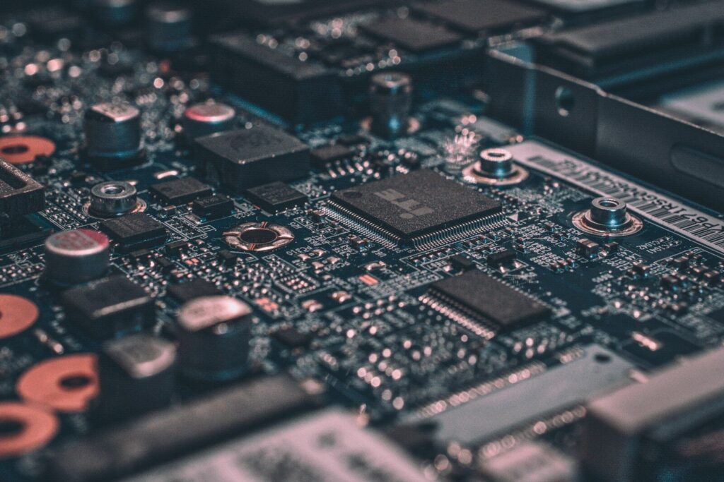
| Category | Typical parts | Job on the board |
|---|---|---|
| Passive | resistors, capacitors, inductors, ferrite beads | store energy, filter noise, limit current |
| Active | diodes, transistors, MOSFETs, integrated circuits | switch, amplify, regulate, compute |
| Electromechanical | connectors, headers, relays, switches, fuses | Join boards, switch loads, protect circuits |
| Timing and sensing | crystals, oscillators, thermistors, hall sensors | Hold clocks, read temperature, and position |
What counts as an electronic component on a PCB
Any part that performs an electrical, electronic, or electromechanical job on the board is an electronic component. Engineers and distributors split them into three broad groups: passive, active, and electromechanical.
The split matters because each group behaves differently in sourcing. Passive parts are cheap and widely stocked, so they rarely cause delays. Active parts carry the intellectual value of the design, they often have long lead times, and they are where counterfeits show up. Electromechanical parts are mechanical first and electrical second, so their failure modes are about wear, vibration, and contact resistance rather than drift.
A dense production board, a printed circuit board (PCB) in the everyday sense, can carry several hundred electronic components across all three groups. A smartphone-class board carries well over a thousand.
Passive electronic components
Passive parts do not need power to do their job, and they cannot amplify a signal. They set the conditions for the rest of the circuit.
- Resistors limit current, divide voltage, and set bias points.
- Capacitors store charge, smooth supply rails, and couple or decouple signals.
- Inductors and ferrite beads suppress high-frequency noise and store energy in switching supplies.
- Crystals and ceramic resonators give microcontrollers a stable clock.
Passives are sold in chip-style packages that sit flat on the board, and they are the parts most often placed by high-speed pick-and-place machines. Reading an electronic PCB component’s name off a laser-etched marking is one of the least reliable ways to identify one, since most markings are abbreviated codes rather than full descriptions.
Active electronic components
Active parts control current flow and need a supply to operate. They are the decision-makers of the circuit.
- Diodes pass current one way and block it the other, which makes them useful for rectification and reverse-polarity protection.
- Transistors and MOSFETs act as switches or amplifiers.
- Voltage regulators turn an input rail into a clean, fixed output.
- Integrated circuits pack thousands or millions of transistors into one package, covering logic, memory, analog, power, and wireless functions.
- Microcontrollers and processors run the firmware that makes the board do something useful.
Electromechanical and interconnect parts
These parts connect the board to the outside world or to another board.
- Board-to-wire connectors and pin headers carry power and signals off the board.
- Relays switch higher loads than the logic side can handle directly.
- Switches, jumpers, and DIP selectors let operators set modes.
- Fuses, TVS diodes, and varistors protect the circuit from overcurrent and voltage spikes.
Their mechanical dimensions matter as much as their electrical ratings. A connector with the wrong retention force or plating will pass bench testing and fail in the field.
A working PCB electronic components list with functions
A practical component list groups the electronic components used in PCB work by function rather than by supplier: protection, power, control, timing, interface, and sensing. Every industrial design uses some subset of that list.
The table below covers the electronic PCB board components that appear in almost every design review, with the job each one does.
| Component | What it does | Where it usually sits |
|---|---|---|
| Resistor | limits current, sets bias, divides voltage | everywhere |
| Capacitor | stores charge, filters rails, couples signals | near every IC supply pin |
| Inductor | stores energy, filters high-frequency noise | switching supplies, inputs |
| Ferrite bead | absorbs high-frequency noise | power entry, cable side |
| Diode | passes current one way, blocks reverse flow | protection, rectifiers |
| LED | emits light as an indicator | panels, status lights |
| Transistor | switches or amplifies small signals | driver stages |
| MOSFET | switches power at speed | motor, heater, LED drivers |
| Voltage regulator | holds a stable output rail | power section |
| Microcontroller | runs firmware and controls peripherals | center of the layout |
| Crystal oscillator | provides a stable clock | next to the controller |
| Connector or header | moves power and signals on and off the board | board edges |
| Relay | switches high current loads from a logic signal | industrial outputs |
| Fuse or TVS | absorbs faults and surges | power input |
| Thermistor or hall sensor | measures temperature or position | sensing points |
Two boards with the same schematic can still differ in cost by a wide margin once package sizes, tolerances, and operating temperature ranges are fixed. That is why a fair quote follows a completed bill of materials, not a product description.
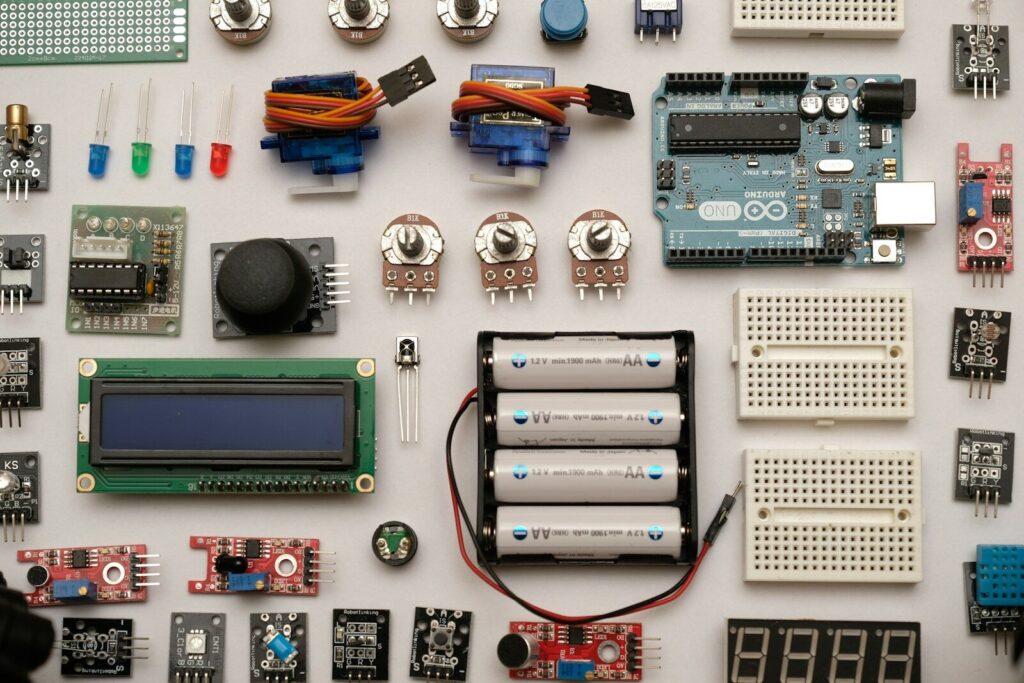
How components get onto the board: through-hole and surface-mount
There are two mainstream mounting methods. Through-hole parts have leads that pass through the board; surface mount parts sit flat on pads. Most modern boards use surface mount for the bulk of the parts, with through-hole reserved for connectors and parts under mechanical stress.
The choice affects tooling, stencil design, inspection method, and rework cost, so it belongs in the design review rather than the production meeting.
Through-hole mounting
Leads go through plated holes and are soldered on the far side, usually by wave soldering or selective soldering. The joint is strong and easy to inspect by eye, and a hand-soldered prototype can be fixed with an iron in minutes. The penalty is board area: every lead needs its own hole, and holes limit how tightly the board can be routed.
Surface mount assembly
Parts are placed onto solder paste printed on pads, then reflowed in an oven. No holes means more routing space, lighter boards, and better high-frequency behavior. It also means the whole build depends on stencil quality, paste volume, and placement accuracy. Placement is fast, but the process window is narrow, and a tombstoned capacitor or a bridged fine-pitch lead will only show up under inspection.
How to choose between them
| Consideration | Through-hole | Surface mount |
|---|---|---|
| Mechanical strength | high, suited to heavy parts | lower, needs pad and via design care |
| Board area used | large | small |
| Assembly speed | slow for high part counts | fast |
| Rework by hand | easy | requires hot air and skill |
| Cost at volume | higher per joint | lower per joint |
| Best fit | connectors, transformers, high-vibration use | dense logic, high-frequency, portable products |
Mixed boards are common and often the right answer: surface mount for the dense logic, through-hole for the connector that gets plugged and unplugged every day.
PCB and PCBA: the difference that changes a quote
A PCB is the bare board with copper traces, pads, and a solder mask but no parts. A PCBA is that board after printed circuit board assembly, meaning components have been soldered on and the unit can be tested as a working circuit.
The distinction decides what you are buying. A bare board quote needs Gerber files, stackup, material, surface finish, and quantity. A printed circuit board assembly quote also needs the bill of materials, the approved manufacturer list, the placement data, and the test specification. Missing any one of those turns into questions, and questions turn into delay. Bare boards and assembly also rarely come out of the same building, which is why printed circuit board manufacturers and assembly houses are usually separate suppliers with separate schedules.
Three documents carry the assembly job:
- The bill of materials lists every part, its reference designator, and its package.
- The Gerber and drill files define the board and its holes.
- The pick-and-place file tells the machine where each part goes.
When those three agree, the line runs. When a footprint in the Gerber does not match the package in the bill of materials, the build stops at the first article inspection. Most faster PCB assembly delays trace back to one of those three documents rather than to machine time.
Component decisions that shape printed circuit board design
Component choice is a design decision, not a purchasing afterthought. Footprints, ratings, thermal load, and availability are all set before the first board is fabricated, and changing them later means a new layout revision.
Good printed circuit board design treats the bill of materials and the layout as one problem.
Footprints and land patterns
A footprint must match the exact package the supplier ships. Manufacturers often offer the same part in several package widths and pin pitches, and a footprint drawn for the wrong variant will not reflow correctly. Standard land patterns published by industry bodies exist for this reason, and the design review should confirm which one the layout follows.
Ratings, derating, and tolerances
A part that runs at 90 percent of its voltage rating on a bench will not survive a hot cabinet. Derating, tolerance stack-up, and temperature coefficient belong in the design notes, especially for power and analog sections.
Thermal load and printed circuit board material
Heat leaves through the board as well as the air, so the printed circuit board material matters. Standard FR-4 laminate covers most industrial electronics. Metal core boards move heat away from LEDs and power devices. Ceramic substrates handle higher temperatures and tighter thermal cycling. Flexible and rigid-flex constructions solve geometry problems that a rigid board cannot.
For the majority of industrial assemblies, the substrate is a rigid laminate, and a rigid PCB manufacturer wholesale supply relationship keeps lead times predictable when volumes rise.
Availability, lifecycle, and second sources
A component that is in stock today can go to allocation next quarter. Checking lifecycle status and identifying pin-compatible second sources at the design stage costs an afternoon. Doing it after a line stops costs weeks. At the other end of the lifecycle, boards that reach recycling are stripped by a PCB electronic components dismantling machine that separates parts and metals from the laminate, which is one more reason to keep part identification documented.
Sourcing electronic components for production
Sourcing is a traceability problem before it is a price problem. The goal is a bill of materials where every line can be traced to an authorized channel and reordered without redesign.
Industrial buyers rarely lose money on the price of a resistor. They lose it on a wrong reel, a counterfeit regulator, or a part that disappears from the market mid-program.
Traceability and authorized channels
Buying through authorized distribution costs more per part and less per program. The paperwork proves the parts are genuine, which matters for medical, automotive, and industrial customers who audit their supply chain. Counterfeit active components are a known problem in open markets, and the failure mode is often a slow drift rather than an immediate stop.
Bill of materials review
A BOM review before quoting catches the expensive mistakes early: obsolete parts, missing package details, parts with no second source, and tolerance conflicts between the schematic and the layout. It also exposes cost reduction options, like consolidating resistor values or moving to a smaller package where the layout allows.
Consignment versus turnkey
Consignment means the customer supplies the parts and the manufacturer assembles them. Turnkey means the manufacturer sources everything and delivers finished boards. Turnkey suits buyers who want one point of responsibility, one invoice, and no risk of parts arriving late. Consignment suits buyers who hold their own stock or have contracted prices.
How SLPCBA handles components, boards, and assembly
SLPCBA runs component sourcing, PCB fabrication, and assembly under one roof, which removes the handover where most schedules slip. Buyers send one package: Gerber files, a bill of materials, and a test specification.
The service covers the full path from prototype to volume:
- Component sourcing through traceable channels, with alternatives proposed when a line item is short.
- Prototype and low-volume builds that use the same process as volume production, so the data carries over.
- Surface mount and through-hole assembly on the same line for mixed boards.
- Turnkey assembly, where the finished board arrives tested and ready for the next stage.
- Wire harness and box-build support when the board needs to leave the factory as part of a larger assembly.
- DFM feedback on footprint, panelization, and placement before tooling is cut.
For buyers who want a single supplier instead of juggling a distributor, a bare-board shop, and an assembler, the certified PCB PCBA manufacturer team at SLPCBA works from the bill of materials rather than from a description. Send the BOM and Gerber files through the contact page, and the quote comes back with component notes, lead time, and any line items that need a decision.
Inspection and testing before boards ship
Every assembled board should be inspected at three levels: solder joint quality, electrical continuity, and functional behavior. Skipping any level moves the failure to the customer’s floor, where it costs far more.
A typical flow looks like this:
- Automated optical inspection after reflow catches missing, misaligned, and tombstoned parts.
- X-ray inspection looks under ball grid arrays and other packages with hidden joints.
- In-circuit test checks each net for shorts, opens, and wrong values.
- Functional test powers the board and exercises its real behavior.
- Final visual and cleanliness checks confirm the finish and the flux residue level.
The acceptability criteria for solder joints come from published industry standards such as the IPC-A-610 family, which defines what counts as a passing joint rather than leaving it to opinion. Boards that go into regulated products often need a documented inspection record alongside the units, and that record starts with a defined test plan.
FAQ
How do I find out which electronic components are on my board?
Read the reference designators printed on the silkscreen, then match them against the bill of materials. If you only have the board and no documents, a reverse-engineering service can extract the netlist and produce a fresh bill of materials by reading the part markings and measuring the circuit. The markings on small packages are often abbreviated, so this works best with the board in hand rather than from photos.
Can a manufacturer source components without a bill of materials?
Not reliably. A schematic or a Gerber file describes connections, not brands, tolerances, or package variants. A supplier can propose a bill of materials from the netlist, but someone still has to confirm the electrical ratings and approve the substitution list. Sending a partial BOM with the critical lines marked is faster than sending nothing.
Why does the same board cost different amounts at different suppliers?
Quotes diverge because of component sourcing routes, board material and layer count, order quantity, test coverage, and how much the supplier does in house. A cheap quote that excludes functional tests or buys components from an open market shifts risk back to the buyer. Compare quotes line by line, including the test plan and the component sourcing terms, rather than comparing the total alone.


