
A printed circuit board (PCB) rarely fails all at once. More often, a single cracked trace, a cold solder joint, or one burned component takes a whole device offline while the rest of the board is perfectly fine. For field engineers, maintenance teams, and procurement managers, knowing how to fix a PCB board is the difference between a quick bench repair and an expensive replacement order. Many boards that look dead are actually repairable with the right approach and a modest set of tools.
You can fix most PCB boards by isolating the fault, cleaning the damaged area, repairing or replacing the broken trace or component, and then retesting the board under load. Simple solder and trace work is doable with basic equipment, while boards with buried layers, fine-pitch BGA parts, or damaged substrate usually need a professional bench. The key is diagnosis before disassembly, because guessing wastes parts and can make the damage worse.
The sections below walk through the tools, typical costs, trace repair, and when to bring in a specialist. For a deeper walkthrough, you can also read our full how-to-repair-PCB guide, which covers bench setup and testing in more detail.
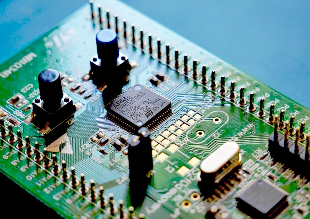
What does fixing a PCB board actually involve
Fixing a PCB board means finding the fault, stopping it from spreading, restoring the electrical path, and proving the repair holds under real operating conditions. It is a diagnostic job first and a soldering job second.
A repair starts with visual inspection. Under good lighting and a loupe or microscope, you look for charring, lifted pads, cracked solder fillets, and bulging components. Many failures announce themselves with a smell or a dark spot before any meter touches the board. After the visible check, you move to electrical testing: a multimeter for continuity and a bench power supply with current limiting for live checks. Some faults only show under load, so a board that passes a cold ohm test can still fail when the system powers on.
Once the fault is located, the actual fix depends on what broke. A lifted pad gets cleaned and reinforced. A cracked trace gets bridged with wire or epoxy-based conductors. A dead capacitor gets swapped for a matching part. The repair is not finished until the board runs in its real environment for a sensible period, because a joint that looks fine cold can open up the moment it heats and flexes.
Documentation matters more than most people expect. A short note on what failed and how it was fixed tells the next technician whether the board has a chronic weakness or just took a one-off hit. For production equipment, that record feeds directly into reliability planning and spare-part stocking.
What tools do you need to repair a circuit board
A reliable circuit board repair bench needs inspection, heating, rework, and test tools, and a basic PCB repair kit covers the majority of field fixes. You do not need a full factory line, but you do need the right items for the board in front of you.
Start with inspection. A 5x to 10x magnifier or a USB microscope shows joints that look fine to the naked eye. Good lighting is not optional, and a helping-hands clamp keeps the board steady while both your hands stay free. For heating, a temperature-controlled soldering station beats a fixed-watt iron every time, because different parts need different tip temperatures.
Rework needs a few specific items:
- Solder wick and a solder sucker for removing old joints
- Lead-free and leaded solder sized to the pad pitch
- A hot-air rework station for surface-mount parts and connectors
- Tweezers, flush cutters, and a scalpel for precise work
- Isopropyl alcohol and a soft brush for cleaning flux and residue
- Conductive epoxy or silver ink for trace bridging
- Jumper wire, ideally 30 AWG, for bypassing damaged paths
Testing closes the loop. A multimeter handles continuity and voltage checks. An oscilloscope helps when the fault is signal-related rather than purely electrical. A current-limited bench supply lets you power a suspect board without letting a short cook it further. A basic PCB repair kit that bundles wick, solder, flux, and a few tips is enough for most consumer and light-industrial boards, while production repair needs the hot-air station and scope as standard.
Slpcba builds boards to IPC acceptance standards, and that discipline shows up on the repair bench too. Boards made with clean laminate, consistent plating, and well-formed pads are far easier to rework than cheap boards with thin finishes and vague footprints. When you are choosing replacement or repair stock, the printed circuit board material and finish directly affect how forgiving the board is under the iron.
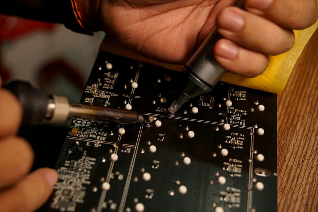
How much does PCB board repair cost
Typical PCB board repair cost runs from about 30 dollars for a simple component swap to several hundred dollars for multilayer or BGA rework, and the real driver is labor plus access to the fault. Parts are usually cheap; the time and equipment are not.
The table below breaks down common repair types by what they tend to cost at a professional bench. These are ranges, not quotes, and they assume the fault is found and the board is clean.
| Repair type | Typical labor time | Approx. cost range | Common constraints |
|---|---|---|---|
| Single component replacement | 15 to 45 minutes | 30 to 90 USD | Standard through-hole or large SMD |
| Trace repair and jumper | 30 to 90 minutes | 50 to 150 USD | Access to both ends of the break |
| Connector or pad rebuild | 1 to 2 hours | 80 to 200 USD | Lifted pads, damaged laminate |
| Multilayer via repair | 2 to 4 hours | 200 to 500 USD | Hidden layers: microsection needed |
| BGA reball or replacement | 2 to 5 hours | 250 to 600 USD | X-ray verification, reflow profile |
A field fix done in-house costs mainly your time, but it carries risk if the technician is not trained. Outsourcing shifts cost to an hourly rate that often lands between 60 and 120 USD depending on region and certification level. When a board is part of a larger assembly, the PCB board repair cost should be weighed against downtime. A line stopped for a day can cost more than ten board repairs, which is why many plants keep a small repair cache on hand.
There is also the hidden cost of a bad repair. A joint that fails a week later can take down the same equipment again and erode trust in the fix. Spending a little more on proper diagnosis and a verified test pass is almost always cheaper than repeating the job. For replacement rather than repair, working with established printed circuit board manufacturers gives you a known-good spare instead of a repaired unknown.
How do you fix a broken trace on a circuit board
You fix a broken trace by exposing clean copper at both ends of the break, bridging the gap with jumper wire or conductive epoxy, and protecting the repair so it cannot short or snap. Knowing how to repair circuit board trace damage is the single most useful bench skill, because traces fail more often than people think.
First, find the break. A continuity test between the two points the trace should connect will show an open where there should be a path. Mark the start and end of the missing section, then gently scrape the solder mask off the copper at each end with a scalpel until you see bright metal. Do not dig into the substrate, because you only need enough pad to attach the bridge.
For a short gap, the cleanest fix is a jumper wire. Cut a length of 30 AWG wire, strip both ends, tin them, and solder one end to each exposed pad. Route the wire away from sharp edges and hot parts, then tack it down with a dot of adhesive so vibration cannot break the joint. For very fine traces where a wire looks out of place, conductive epoxy or silver ink can rebuild the conductor directly along the original path. That method needs a steady cure time and a careful coat, but it keeps the board looking close to original.
After the bridge is in, test continuity again before power is applied. Then protect the work. A thin coat of conformal-style lacquer or UV solder mask over the repaired section stops corrosion and accidental shorts. If the trace carried real current, check that the wire gauge matches what the original copper could handle, because a thin jumper on a power line will just burn out again.
Trace repair is where printed circuit board design decisions from the original layout matter. Boards with wide power traces, tear-drop pad transitions, and sensible spacing are easier to bridge cleanly.
When should you hire a circuit board repair technician
You should hire a circuit board repair technician when the fault sits under a BGA, inside a buried layer, or on a board where a wrong move costs more than the repair itself. Knowing your limit protects the asset.
Some signs are clear. If the component is a ball-grid array with no leads to touch, you need hot-air rework, a stencil, and often an X-ray to confirm the joints. If the board is a multilayer design and the failure is an internal via, no bench tool can reach it without microsectioning, which means a specialist or a replacement is needed. If the equipment is safety-critical, medical, or aerospace-linked, certified repair is not a preference but a requirement, and a trained circuit board repair technician working to IPC-A-610 is the only sensible route.
Other signs are about your own capacity. If you have spent an hour and still cannot locate the fault, a professional bench with thermal cameras and boundary-scan tools will likely find it faster than another guess. If the board keeps failing in the same place, the problem is systemic, not a single part, and a technician can tell you whether the design, the environment, or the component batch is at fault.
Cost also sets the line. When the PCB board repair cost at a certified shop approaches the price of a new board, compare the two with downtime included. A rigid PCB manufacturer like SLPCBA can often turn a replacement faster than a slow repair queue, and a fresh board removes the risk of a recurring weakness. For production lines, keeping a small stock of known-good spares is usually cheaper than betting on a single repaired unit.

Can you repair a board through proper printed circuit board assembly
Good printed circuit board assembly is itself a form of repair prevention, because a board built correctly from the start fails less and reworks more cleanly when it does. The link between assembly quality and fixability is closer than it looks.
Assembly quality starts with the bare board. The printed circuit board material sets how the laminate behaves under heat and flex, and a stable substrate resists the warping that cracks joints over time. FR-4 covers most needs, while ceramic, metal-core, and high-frequency laminates serve thermal or RF jobs where standard material would drift. Picking the right base during design is cheaper than fighting failures after the fact.
Placement and soldering discipline matter just as much. A proper printed circuit board assembly run uses controlled reflow profiles, correct paste volume, and post-build inspection so cold joints and tombstones never ship. When a board is built this way, a later repair is a clean swap rather than a fight against poor original work. Slpcba runs prototypes through volume assembly under the same process controls, so the board you repair in the field matches the board that left the line.
There is also a design angle. Printed circuit board design that leaves test points, avoids routing traces under heavy components, and uses sensible thermal relief on pads makes fault-finding faster and rework safer. When you are repairing a board that was never designed to be opened, every step is harder. When the layout is planned for service, the same fix takes minutes. If you are specifying a new board, fold those serviceability rules into the design brief rather than treating repair as someone else’s problem.
How do you choose the right printed circuit board manufacturers for replacement
Choose printed circuit board manufacturers on process control, certification, and turnaround, not just unit price, because a replacement board is only as good as the line that built it. When repair is not worth it, the next step is a better spare.
Start with capability fit. A simple double-sided board needs a different shop than a 10-layer HDI stack with impedance control. Ask what the manufacturer actually runs day to day, because a shop stretched beyond its comfort zone ships inconsistent products. Certifications matter for serious work: IPC and ISO alignment signal that the line follows documented processes rather than hope. SLPCBA serves prototype to volume across rigid, flex, and rigid-flex builds, which means one partner can cover a one-off repair spare and a production reorder.
Lead time decides whether replacement beats repair. If a new board takes six weeks and the line is down now, a faster repair or a local cached spare wins. If the board is a steady consumable, a manufacturer with a repeatable build and stored gerbers keeps future spares cheap and identical. Price should include the finished and tested board, not just bare fabrication, because a board that arrives untested just moves the risk to your bench.
Material and finish are the quiet differentiators. The printed circuit board material, copper weight, and surface finish set solderability and field life. A manufacturer that lets you specify these and holds them batch to batch gives you a spare that behaves like the original. When you are ready to spec a replacement or a small repair-run batch, reach out for custom PCB quotes and share the Gerber or the failed board so the new unit matches what your equipment expects.
FAQ
Can a PCB with a burnt spot be repaired, or should it be replaced?
A small burnt spot on the surface can often be cleaned, the damaged trace or pad rebuilt, and the board returned to service if the substrate underneath is still solid. If the charring goes deep, the laminate has lost its insulation, and the board should be replaced because hidden shorts will keep returning.
Is it worth learning to fix PCB boards in-house for a small team?
For teams that run repeated equipment, yes. A basic bench and a trained person recover many boards that would otherwise be scrapped, and the savings on spares and downtime usually pay for the tools within a few jobs. The limit is complex parts like BGAs and buried-layer faults, which stay better suited to a specialist.
What is the most common cause of PCB failure that is actually fixable?
Cold and cracked solder joints top the list, followed by damaged traces from flex and impact. Both are repairable with standard tools and make up a large share of field failures, which is why a solid PCB repair kit and basic rework skills cover most real-world fixes.