
Batteries soldered straight to a printed circuit board sit inside almost every portable device we use. Smartphones, laptops, cordless tools, medical monitors, and small IoT sensors all rely on a battery pack that is welded or soldered to the board rather than plugged in with a connector. When that pack ages, swells, or simply needs to come off for board-level rework, you end up with a power source fused to copper by solder. Getting it off without cracking the laminate or cooking the cells is one of the most common repair problems people hit, and our How to Desolder PCB walkthrough covers the broader technique if you want the full background.
You can desolder a battery pack from a PCB by first cutting all power and isolating the cells, then melting each solder joint with a soldering iron, hot air station, or desoldering tool while you lift the terminals clear. Work slowly; keep the heat as low as the joint allows; and never let a lithium cell short, puncture, or overheat, because a damaged cell can swell, vent gas, or ignite. Once the joints release, clean the pads, check the surrounding traces, and only then fit a replacement pack or route the board to rework.
The sections below cover the tools you need, the step-by-step removal method, the mistakes that ruin boards, and how the type of PCB under the pack changes the way you work.
Why battery packs are soldered to PCBs
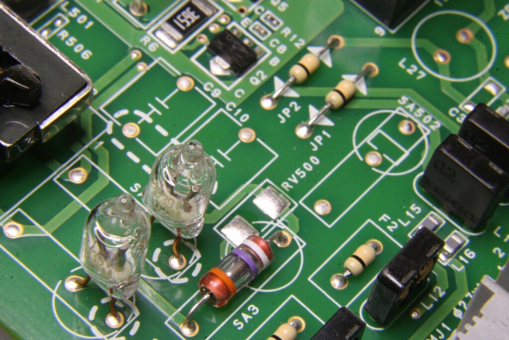
Battery packs are soldered to PCBs because soldered joints carry high current, survive vibration, and take far less space than a plug-in connector, which matters most in compact or sealed products.
Most consumer and industrial devices need the battery to move current in and out of the board many times a day. A soldered joint does this job with very low resistance and no loose contact that could rattle loose. In a power tool or an e-bike control board, the pack can pull several amps, and a weak connector would heat up and fail long before the cells do.
Common battery pack mounting styles
Battery packs reach the board in a few ways. The simplest method is a pair of tinned leads that the assembler solders into plated through-holes. A second style uses metal tabs or nickel strips spot-welded to cylindrical cells and then soldered to the board. A third style, common in thin devices, bonds a pouch cell’s tabs directly to pads on a flexible or rigid PCB. Each style changes how you approach removal, because a welded tab needs more heat than a thin lead, and a pouch tab tears easily if you pull too early.
Why manufacturers skip connectors
Connectors cost space, height, and money. In a hearing aid or a smart tag, there is no room for a battery socket, so the cell is bonded straight to the board. Soldering also gives a tighter seal against dust and moisture, which helps in outdoor and medical gear. The trade-off is repair difficulty: a soldered pack is cheap to build but hard to swap, which is exactly why rework guides like this one exist and why a printed circuit board design aimed at serviceability should leave a little lead length for the next technician.
What tools you need to desolder a battery pack
You need a temperature-controlled soldering iron or hot air station, desoldering braid or a vacuum pump, flush cutters, isopropyl alcohol, and eye protection before you touch the board.
The right tools decide whether removal takes five minutes or ends in a ruined board. A fixed-power iron runs too hot and scorches the laminate, while a controlled station lets you set the tip near the solder’s melt point and back off the moment the joint gives. The table below maps each tool to the job it does best.
| Tool | Best used for | Why it matters |
| Temperature-controlled iron | Single through-hole leads and small pads | Sets a known tip temperature so you do not overshoot the solder melt point |
| Hot air station | Surface-mount tabs and pouch foils | Spreads heat evenly and lifts the joint without prying |
| Desoldering gun or pump | Plated holes you want to be reusable | Pulls molten solder out of the hole for a clean pad |
| Desoldering braid | Leftover surface solder | Wicks up residue after the pack is clear |
| Flush cutters | Trimming leads before removal | Stops loose wire from snagging traces |
| Isopropyl alcohol and brush | Post-removal cleanup | Removes flux and leaked electrolyte |
| Multimeter | Verification | Confirms the pack is fully disconnected |
Heating tools
A fine conical or chisel tip on a soldering iron handles single through-hole leads well. For surface-mount tabs and pouch-cell foils, a hot air station with a narrow nozzle spreads heat evenly and lifts the joint without prying. A dedicated desoldering gun pulls molten solder straight out of the hole, which is the cleanest option when the pack uses plated holes and you want the board reusable for a fresh pack or a new printed circuit board assembly run.
Removal and cleanup tools
Keep desoldering braid (wick) on hand to soak up leftover solder and flush cutters to trim leads before they snag. After the pack is off, scrub the area with isopropyl alcohol and a soft brush to remove flux and any leaked electrolyte. A multimeter helps you confirm the pack is fully disconnected and that no trace still carries voltage, which is the check most people skip and later regret.
Safety gear
Lithium cells can fail violently if punctured or shorted, so wear eye protection and work in a clear space away from flammables. Have a small fire-safe container or sand nearby in case a cell vents. Never cut through a live pack, and never let your iron tip bridge two terminals. If you smell a sweet solvent odor, stop at once, because that is the smell of a venting cell.
How to desolder a battery pack from a PCB step by step
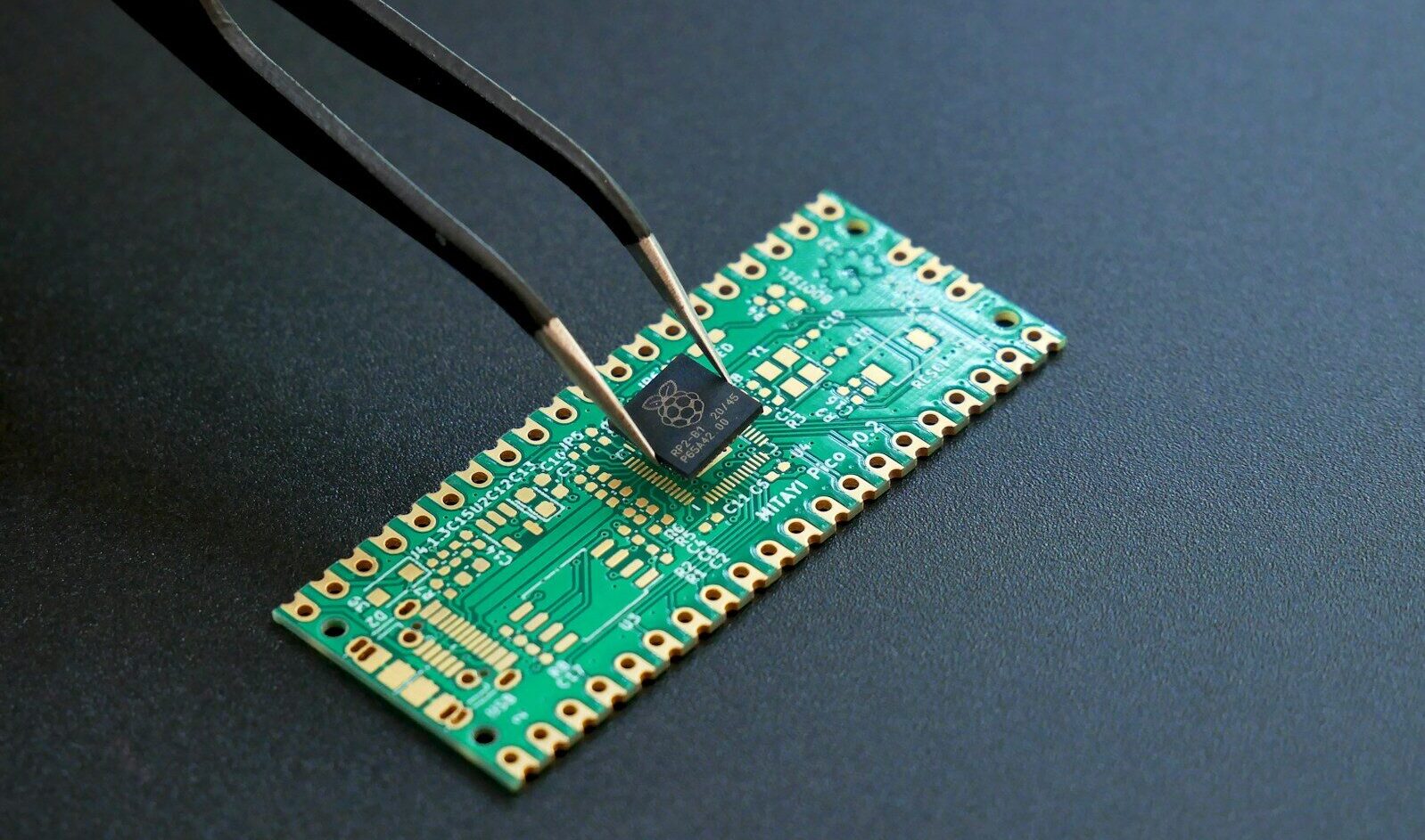
Remove the pack by isolating the cells first, then heating each joint just until the solder flows, lifting the terminal, and repeating until every connection is free, followed by pad cleaning and a close inspection.
Follow the order below and resist the urge to rush. Heat is the only thing freeing the joint, and too much of it is what destroys boards. The method is the same whether the base is a rigid PCB or a flex PCB, but the heat budget shifts with the material.
Preparation and inspection
Start by powering down the device and, where possible, discharging the pack through its normal load or a resistor. Photograph the wiring so you can refit it later. Identify each connection: positive lead, negative lead, thermistor, and any balance wires. Mark them. Check the board for a rigid PCB, a flex section, or a rigid-flex build, because that tells you how much heat the base material can take and whether you should support a thin tail while you work.
Releasing the solder joints
Set your iron to roughly 320 to 350 degrees Celsius for lead-free solder, or about 280 degrees for tin-lead. Touch the joint, add a tiny bit of fresh solder to help heat transfer, and the moment the old solder shines and moves, lift the terminal with tweezers or push the lead out from behind with the iron. For surface pads, sweep hot air at a low flow until the foil releases, then lift gently. Work one joint at a time and let the board cool between them so heat does not build up in one spot.
Cleaning and inspecting the pads
Once the pack is clear, drag desoldering braid over each pad to pull residual solder, then clean with isopropyl alcohol. Look for lifted pads, charred laminate, or cracked traces around the site. A rigid PCB usually survives a small mistake; a thin flex or rigid-flex section may delaminate if it gets too hot, so inspect those areas closely. Only proceed to rework when every pad is flat and every trace is intact, because a hidden lift will fail the moment the new pack draws current.
Mistakes that damage the board or the battery
The failures that matter are overheating the laminate until it delaminates and shorting or puncturing a cell, because both turn a simple rework into a scrapped board or a fire risk.
Most ruined jobs come from impatience. People hold the iron on a joint too long, or they yank a lead that has not fully melted, and the pad rips off the board. A few habits remove almost all of that risk.
Overheating the laminate
Every PCB has a glass-epoxy or polyimide base with a temperature limit. Push past it, and the layers separate, the copper lifts, and the board is done. High-speed PCB and high-frequency PCB designs are especially sensitive because their thin dielectric and tight impedance control lose function the instant the material warps. Keep dwell time short and let the joint tell you when it is ready rather than forcing it with extra heat.
Shorting or puncturing cells
A metal tool bridging the pack’s terminals dumps current straight through your tweezers and can weld them shut or spark. A slipped blade can puncture a pouch or cylindrical cell and release flammable vapor. Always cut one lead at a time, keep metal away from both terminals at once, and treat a swollen cell as already failed: stop, isolate it, and dispose of it by local battery rules. A pack that feels warm or looks puffy should never go near a heat source.
How PCB type changes the desoldering method
The board under the pack sets your heat budget and your margin for error, so a rigid board tolerates more, while flex, rigid-flex, and ceramic builds demand lower, better-controlled heat.
Not every PCB reacts the same to a hot iron. The base material, layer count, and copper weight all change how fast heat spreads and how badly the board suffers if you overdo it. Matching your method to the board is the difference between a clean removal and a write-off.
Rigid and flex boards
A standard rigid PCB with FR-4 handles rework best because the material is stable and the copper bonds firmly. A flex PCB or a rigid-flex PCB is more challenging: the polyimide film is thin and tears if you pull a terminal before the solder is fully liquid. On a rigid-flex build, heat the joint from the rigid side where you can, support the flex tail so it does not fold, and use the lowest airflow that still releases the foil. A torn flex layer is hard to repair and often means a new board.
High-frequency and high-speed boards
High-speed PCB and high-frequency PCB layouts carry RF or fast digital signals on controlled-impedance traces. Excess heat can shift the dielectric constant or lift a ground plane, which quietly breaks performance even when the board looks fine. Keep the iron tip small, avoid wide preheating, and prefer hot air at a tight, low setting so you affect only the joint you are freeing. HDI PCBs add another wrinkle, because their microvias are fragile, and a hot tip can collapse a buried connection next to the pack pads.
Metal core and ceramic boards
A metal-core PCB spreads heat fast because its aluminum base pulls warmth away from the tip, so joints there need a hotter iron held a touch longer, yet the board itself stays safe. A ceramic PCB is brittle and cracks under sudden temperature change, so warm it gently on a preheater, lift the joint with minimal force, and let it cool slowly. These two sit at opposite ends of the heat spectrum and reward patience at both. When the pack sits on a ceramic PCB, a gradual ramp beats a quick blast every time.
Reworking or replacing after removal
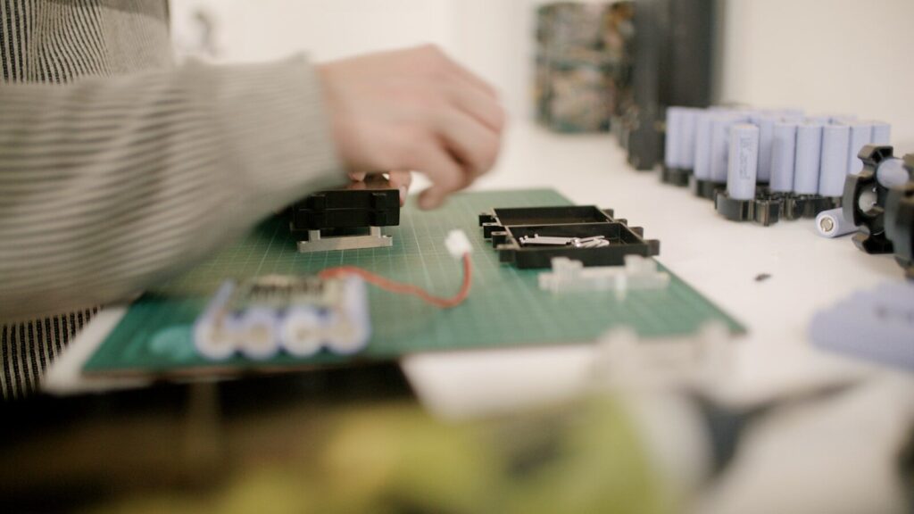
After the old pack is off, fit the new pack by matching the original polarity and lead order, then test the board under load before you close the device.
Removal is only half the job. A clean board with the wrong pack wired backward fails just as fast as a scorched one, so the refit deserves the same care as the takeoff.
Fitting a new pack
Solder the replacement leads in the same order your photo showed, tin the tips first, and keep each joint brief. If the design used a thermistor or balance wire, reconnect it exactly, because skipping it removes the safety signal the charger relies on. For a pouch cell on a flex or rigid-flex PCB, use just enough heat to seat the tab and no more, then add a dab of adhesive so the cell cannot shift and stress the joint during use.
Testing the repaired board
Power the board through a current-limited supply and watch the draw. Confirm the pack voltage, check that nothing warms unexpectedly, and run the device through a short cycle. A printed circuit board design that passed assembly can still fail rework if a trace was nicked, so a quick functional test beats a visual guess. If the board draws more than expected, recheck the pack polarity before you trust the repair.
Sourcing parts and rework support
When the pack or the board needs replacement rather than repair, source verified cells and professional assembly from a partner that builds to spec and can rework your design.
Finding the right parts is often harder than the desoldering. Cells must match capacity and discharge rating, and the board may need a fresh run if pads were lost. A reliable build starts with the right electronic components and a board made to handle the current your pack draws.
Faster PCB assembly is where SLPCBA helps most: the team runs turnkey PCB assembly for prototypes and production, builds rigid, flex, and rigid-flex boards, and can rework soldered battery interfaces to your drawing. If your design uses a high-speed PCB, a metal-core PCB, or a ceramic PCB, the engineers match the base material and stack-up to the job instead of forcing one approach on every board. That material-first thinking is what keeps a reworked pack stable under real load.
For ongoing work, printed circuit board manufacturers that hold IPC-style process control give you traceable quality and fewer field returns, and you can read the relevant assembly standards at IPC. Slpcba also supports printed circuit board material selection and printed circuit board design review, so a pack that was hard to remove once can be made easier to service in the next revision. When you need cells, a rework run, or a full assembly quote, reach out through the contact page and share your files for a fast response.
Desoldering a battery pack from a PCB is a job of patience more than force. Cut the power, isolate the cells, free one joint at a time, and let the board cool between passes. Match your heat to the board type, keep metal off both terminals at once, and test before you close the case. Do that, and most soldered packs come off cleanly enough to reuse the board or fit a fresh one with confidence.
Frequently asked questions
Is it safe to desolder a lithium battery pack from a PCB at home?
It can be safe if you work on a discharged pack, wear eye protection, and keep each cell from shorting or puncturing, but the risk is real because lithium cells can vent or ignite when damaged. If the pack is swollen, warm, or leaking, stop and treat it as failed rather than applying heat. A current-limited bench supply and a fire-safe workspace remove most of the danger for small packs.
What temperature should I set my soldering iron to desolder battery leads?
For lead-free solder, roughly 320 to 350 degrees Celsius works for most through-hole leads, while tin-lead flows near 280 degrees. The exact number matters less than dwell time: touch the joint, let the solder shine, and lift the moment it moves. On a flex, rigid-flex, or ceramic PCB, drop the temperature and add a preheater so you protect the base material.
Can I reuse the PCB after removing a soldered battery pack?
You can reuse the board when every pad stays flat, no trace is cracked, and the laminate shows no char or lift after cleaning. Inspect the site under good light and confirm with a multimeter that the pack circuit is fully open. If a pad tore off or a via collapsed, the board usually needs a fresh run rather than a repair, especially on HDI PCBs where the damage hides inside the stack-up.